26-4 9424200996
Logic Timers (62) BE1-11m
Block input to the desired logic in BESTlogicPlus. When the element is initially selected from the
Elements view, the default condition of the Block input is a logic 0.
Logic Connections
Logic timer element logic connections are made on the BESTlogicPlus screen in BESTCOMSPlus. The
logic timer element logic block is illustrated in Figure 26-7. Logic inputs and outputs are summarized in
Table 26-1.
Figure 26-7. Logic Timer Element Logic Block
Table 26-1. Logic Inputs and Outputs
Starts the 62 timing sequence
Disables the 62 function when true
True when 62 timing criteria have been met according to mode
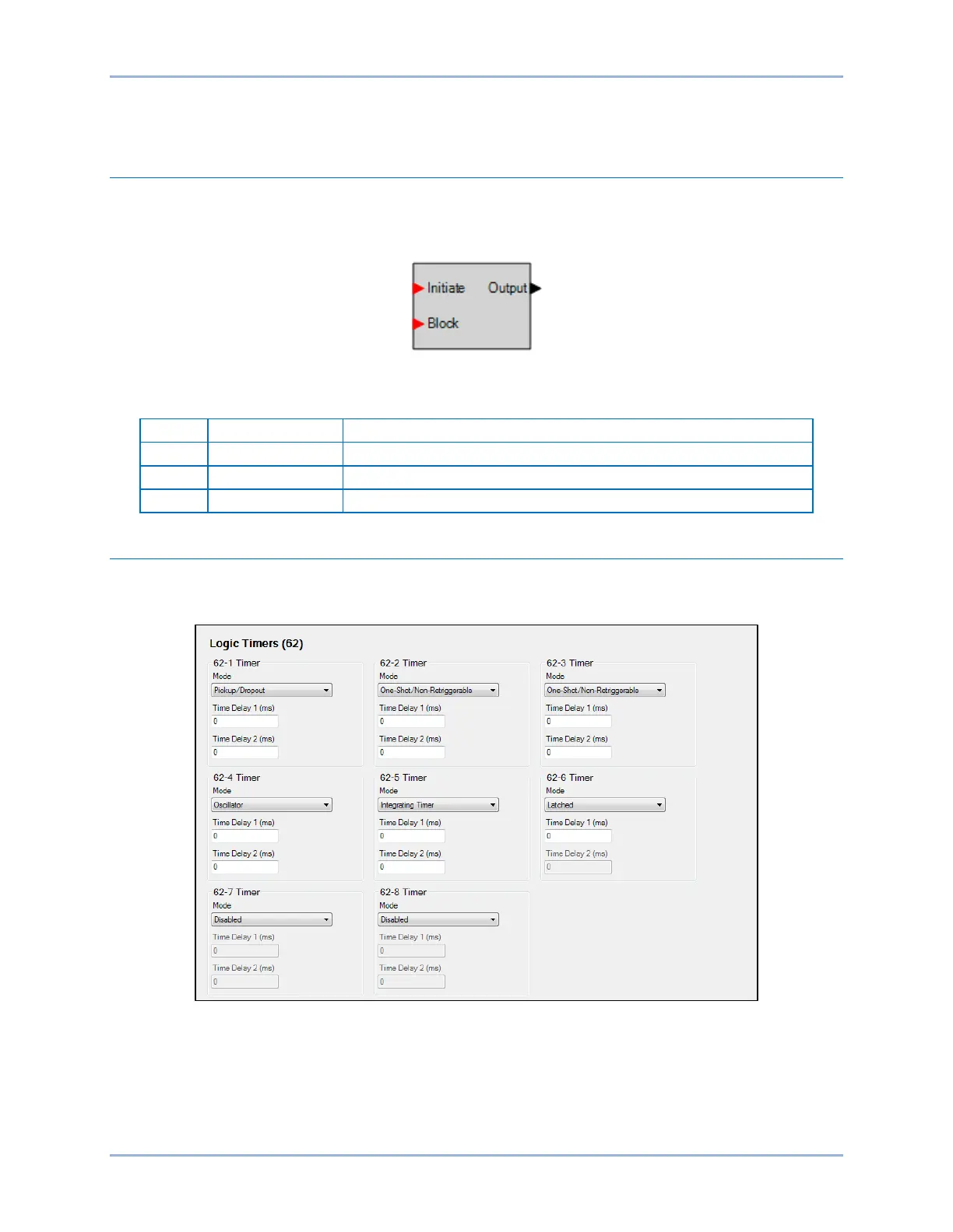
Operational Settings
Logic timer element operational settings are configured on the Logic Timers (62) settings screen (Figure
26-8) in BESTCOMSPlus.
Figure 26-8. Logic Timers Settings Screen