9424200996 45-3
BE1-11m Terminals and Connectors
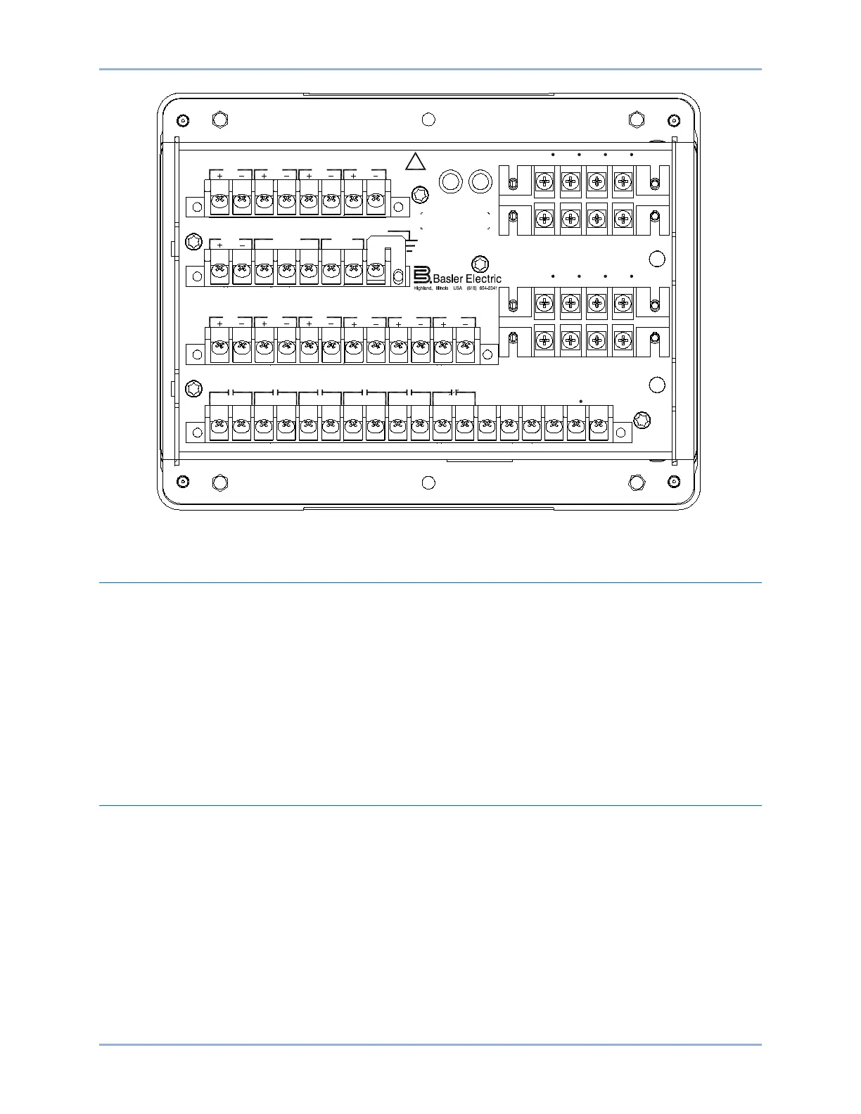
Figure 45-4. Rear Panel Connections with Fiber Optic Ethernet (10 Inputs and 5 Outputs Option)
Terminal Blocks
J style cases use two sizes of terminal blocks.
The terminal blocks used for current sensing connections use #8-32 screws with lock washers. The lock
washer is an integral part of the current-sensing wiring system and must not be removed. Without the lock
washer, the terminal screw may bottom out and prevent a tight fit against the lug. The torque applied to
the terminal screws should not exceed 15 inch-pounds (1.69 N•m). Each terminal block screw
accommodates a lug no wider than 0.344 inches (8.6 millimeters).
All other terminal blocks use #6-32 screws. The torque applied to these screws should not exceed 12
inch-pounds (1.35 N•m). Each terminal block screw accommodates a lug no wider than 0.320 inches (8.1
millimeters).
CT Polarity
CT polarity is critical to the proper operation of the BE1-11m. The following provides fundamental
information on CT polarity and protective systems.
By ANSI convention, current transformer polarity will face away from the protected winding of a
transformer, motor, generator, or reactor, and away from the contacts in a circuit breaker. Therefore,
primary current flow towards the winding or contacts (direction of protected zone) will result in a
secondary current out X1, in phase with the primary (see Figure 45-5 and Figure 45-6).
On occasion, however, protection engineers will encounter situations where CT polarity is reversed for a
specific application. That is, non-polarity of the CT secondary will be in phase with the primary current
flow (Figure 45-7). For example, a transformer differential CT from a breaker with a different polarity
convention such as low voltage switchgear, or a bus differential CT taken from the low side of a
transformer.
!
WARNING
BE1-11
C12C11C10C9C8C7C6C5C4C3C2C1 C13 C14 C15 C16 C17 C18
V
A
OUT 2 OUT 3 OUT 4 OUT 5OUT 1 ALARM V
B
V
C
V
X
V
X
N
E12E11E10E9E8E7E6E5E4E3E2E1
IN5
IN6
IN7
A8A7A6A5A4A3A2A1
IRIG PWR
C
A B
RS-485
GND
B8B7B6B5B4B3B2B1
IN1 IN2
IN3
IN4
D1 D3 D5 D7
I
A1
I
B1
I
C1
I
G1
I
A1
D2 D4 D6 D8
I
B1
I
C1
I
G1
I
A2
F2 F4 F6 F8
I
B2
I
C2
I
G2
F1 F3 F5 F7
I
A2
I
B2
I
C2
I
G2
ETHERNET
TX RX
IN8 IN9 IN10
P0082-21