EasyManua.ls Logo

Baumer VCXG - Pin Assignment and LED Signaling; VCXG Ethernet Interface (PoE); VCXG Power Supply and IOs; VCXG GPIO Input;Output

Baumer VCXG
78 pages
Print Icon
To Next Page IconTo Next Page
To Previous Page IconTo Previous Page
Loading...
15
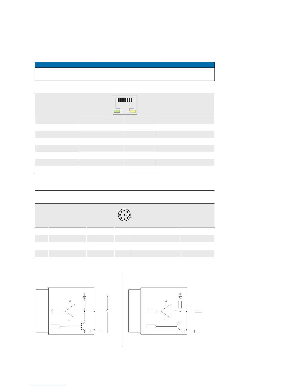
7. Pin-Assignment / LED-Signaling
7.1 VCXG
7.1.1 Ethernet Interface (PoE)
Notice
The camera supports PoE (Power over Ethernet) IEEE 802.3af Clause 33, 48V Power
supply.
8P8C Modular Jack (RJ45) with LEDs
1
8
1 green/white MX1+ (negative / positive V
port
)
2 green MX1- (negative / positive V
port
)
3 orange/white MX2+ (positive / negative V
port
)
4 blue MX3+
5 blue/white MX3-
6 orange MX2- (positive / negative V
port
)
7 brown/white MX4+
8 brown MX4-
7.1.2 Power Supply and IOs
Power Supply / Digital IOs (on camera side)
wire colors of the connecting cable (ordered separately)
8
5
7
3
1
4
2
6
1 GPIO (Line2) white
5 Power VCC OUT1
grey
2 Power V
CC
brown
6 OUT1 (Line3)
pink
3 IN1 (Line0)
green
7 GND (Power, GPIO)
blue
4 GND IN1
yellow
8 GPIO (Line1)
red
7.1.3 GPIO (General Purpose Input/Output)
Input
300
Output
Pin 1 / 8
3.3 V
3.3 V
FPGA
FPGA
FPGA
FPGA
Pin 7
Pin 1 / 8
Pin 7
Ω
300
Ω
High:
2.4 .. 3.3 V
I sink max.
= 50 mA
Low:
0 V .. 0.4 V
Low:
0 V .. 0.8 V
High:
2.0 V .. 30 V

Table of Contents

Related product manuals