55
9.6.6 Timers
Timers were introduced for advanced control of internal camera signals.
For example the employment of a timer allows you to control the ash signal in that way,
that the illumination does not start synchronized to the sensor exposure but a predened
interval earlier.
On Baumer VCX cameras the timer conguration includes four components:
igger
t
TimerDuration
t
TimerDelay
Component Description
TimerTriggerSource This feature provides a source selection for each timer.
TimerTriggerActivation This feature selects that part of the trigger signal (edges or
states) that activates the timer.
TimerDelay This feature represents the interval between incoming trigger
signal and the start of the timer.
TimerDuration By this feature the activation time of the timer is adjustable.
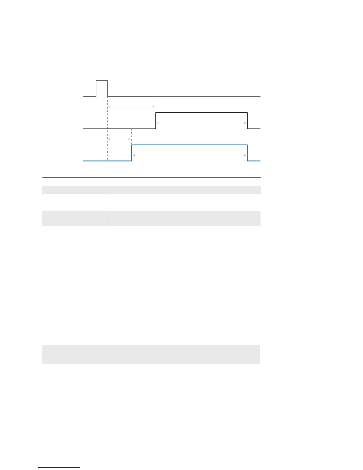
9.6.6.1 ExposureActiveDelay
As previously stated, the Timer feature can be used to start the connected illumination
earlier than the sensor exposure.
This implies a timer conguration as follows:
▪ The ash output needs to be wired to the selected internal Timer signal.
▪ Trigger source and trigger activation for the Timer need to be the same as for the
sensor exposure.
▪ The TimerDelay feature (t
TimerDelay
) needs to be set to a lower value than the trigger
delay (t
triggerdelay
).
▪ The duration (t
TimerDuration
) of the timer signal should last until the exposure of the sensor
is completed. This can be realized by using the following formula:
t
TimerDuration
= (t
triggerdelay
– t
TimerDelay
) + t
exposure
9.6.7 Frame Counter
The frame counter is part of the Baumer image infoheader and supplied with every image,
if the chunkmode is activated. It is generated by hardware and can be used to verify that
every image of the camera is transmitted to the PC and received in the right order.
◄Figure43
Possible Timer congu-
ration