63
10.4.2 CongurationExample
For the three employed cameras the following data are known:
Camera
Model
Sensor
Resolution
[Pixel]
Pixel Format
(Pixel Depth)
[bit]
Resulting
Data Volume
[bit]
Readout
Time
[msec]
Exposure
Time
[msec]
Transfer
Time (GigE)
[msec]
VCXG-53M 2592 x 2048 8 42467328 35.3 20 ≈ 39.55
VCXG-53M 2592 x 2048 8 42318976 35.3 20 ≈ 39.55
VCXG-53M 2592 x 2048 8 42318976 35.3 20 ≈ 39.55
▪ The sensor resolution and the readout time (t
readout
) can be found in the respective
Technical Data Sheet (TDS). For the example a full frame resolution is used.
▪ The exposure time (t
exposure
) is manually set to 35.3 msec.
▪ The resulting data volume is calculated as follows:
Resulting Data Volume = horizontal Pixels × vertical Pixels × Pixel Depth
▪ The transfer time (t
transferGigE
) for full GigE transfer rate is calculated as follows:
Transfer Time (GigE) = Resulting Data Volume / 1024
3
× 1000 [msec]
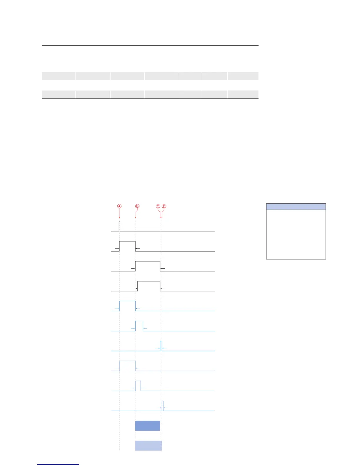
All the cameras are triggered simultaneously.
The transmission delay is realized as a counter, that is started immediately after the sen-
sor readout is started.
Camera 1
(TXG13)
Trigger
Camera 2
(TXG06)
Camera 3
(TXG03)
t
exposure(Camera 1)
t
exposure(Camera 2)
t
exposure(Camera 3)
t
readout(Camera 3)
t
transferGigE(Camera 3)
t
readout(Camera 2)
t
transferGigE(Camera 2)
t
readout(Camera 1)
t
transfer(Camera 1)*
TransmissionDelay
Camera 2
TransmissionDelay
Timings:
A - exposure start for all
cameras
B - all cameras ready for
transmission
C - transmission start
camera 2
D - transmission start
camera 3
* Due to technical issues
the data transfer of
camera 1 does not take
place with full GigE
speed.
◄Figure51
Timing diagram for the
transmission delay of
the three employed
cameras, using even
exposure times.