50
9.6 Process Interface
9.6.1 Digital IOs
9.6.1.1 UserDenableInputs
The wiring of these input connectors is the responsibility of the user.
The sole exception to this is the compliance with predetermined high and low levels
(only the optical input IN1; 0 ... 4.5V low, 11 ... 30V high).
The dened signals will have no direct effect, but can be analyzed and processed on the
software side and used to control the camera.
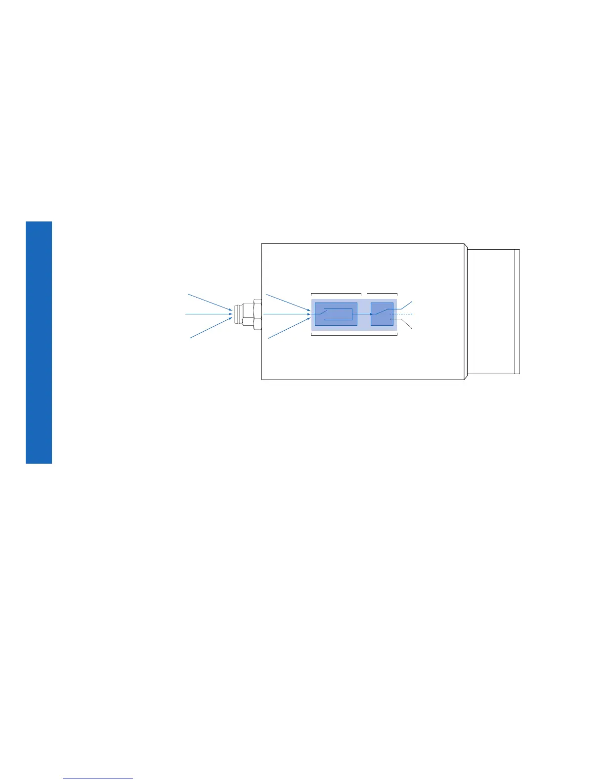
Using a so called "IO matrix" allows you to select the signal and the state to be processed.
On the software side, the input signals are named "Trigger", "Timer" and "LineOut 1...3".
* Example, if the two GPIO's are used as input.
(Input) Line 1*
(Input) Line 0
(Input) Line 2*
Trigger
Timer
Events
state high
state low
IO Matrix
state selection
(inverter)
signal selection
(software side)
Figure38►
IO matrix on the input
side.