61
10.3.1 Example 1: Multi Camera Operation – Minimal IPG
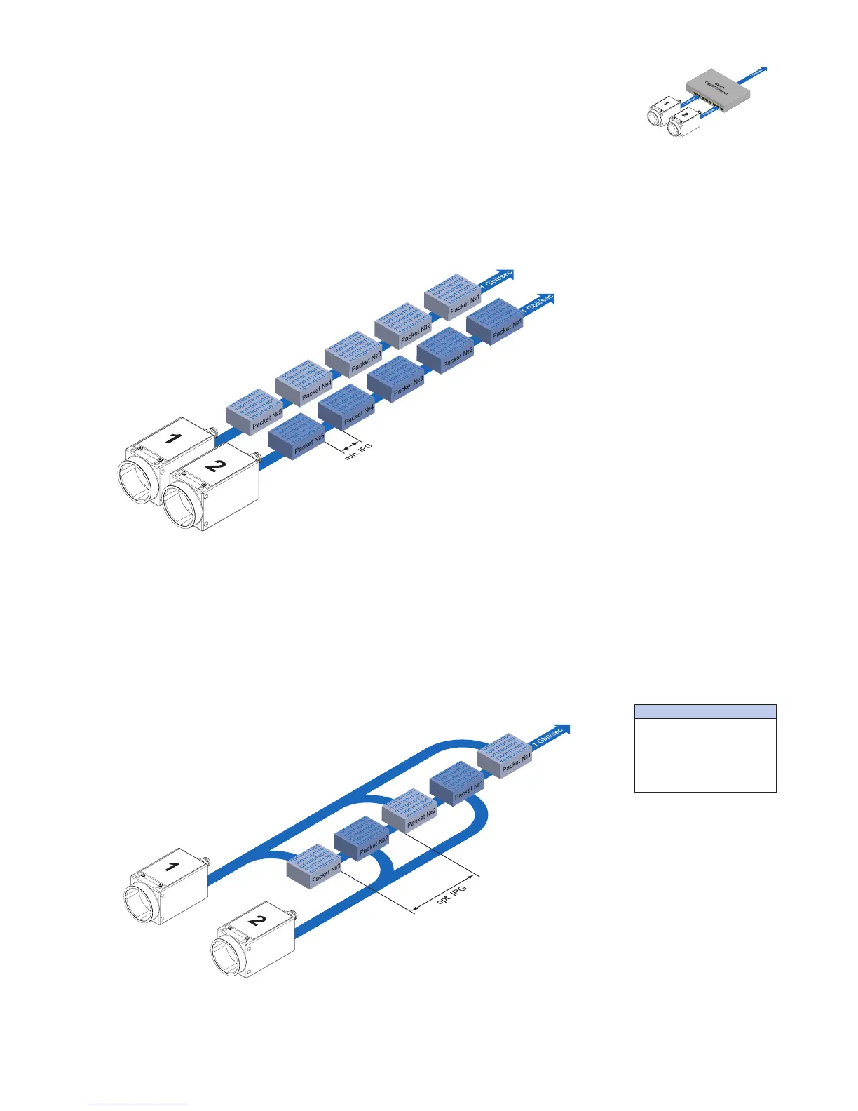
Setting the IPG to minimum means every image is transfered at maximum speed. Even
by using a frame rate of 1 fps this results in full load on the network. Such "bursts" can
lead to an overload of several network components and a loss of packets. This can occur,
especially when using several cameras.
In the case of two cameras sending images at the same time, this would theoretically oc-
cur at a transfer rate of 2 Gbits/sec. The switch has to buffer this data and transfer it at a
speed of 1 Gbit/sec afterwards. Depending on the internal buffer of the switch, this oper-
ates without any problems up to n cameras (n ≥ 1). More cameras would lead to a loss of
packets. These lost packets can however be saved by employing an appropriate resend
mechanism, but this leads to additional load on the network components.
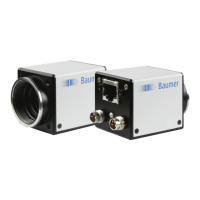
10.3.2 Example 2: Multi Camera Operation – Optimal IPG
A better method is to increase the IPG to a size of
optimal IPG = (number of cameras-1)*packet size + 2 × minimal IPG
In this way both data packets can be transferred successively (zipper principle), and the
switch does not need to buffer the packets.
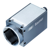
▲Figure46
Operation of two camer-
as employing a Gigabit
Ethernet switch.
Data processing within
the switch is displayed
in the next two gures.
◄Figure47
Operation of two cameras em-
ploying aminimal inter packet
gap (IPG).
◄Figure48
Operation of two camer-
as employing an optimal
inter packet gap (IPG).
Max. IPG:
On the Gigabit Ethernet
the max. IPG and the data
packet must not exceed 1
Gbit. Otherwise data pack-
ets can be lost.