NOTE!
The mapping cannot be changed in state NMT_CS_OPERATIONAL. A new map-
ping will be activated only after transiti
on to NMT_CS_READY_TO_OPERATE.
Data Exchange and Parameterization
Application Manual POWERLINK Controlled Node
Document no. 5.13013.04
39
of 80
5
A maximum of 1490 bytes are provided by the PReq respectively the PRes data frame
for the payload data transmission. The POWERLINK Controlled Node is able to transmit
the contents of up to eight variables / objects in each direction. The logic content of the
user data is determined by the mapping.
Specific information about the objects to be mapped are needed for this determination:
Object index, subindex and the length of the da
te as well as the sequence of the objects
to be mapped. The objects to be mapped are written from the object directory to the sub-
indices starting with 0x01 of the mapping object (0x1600, 0x1A00), e. g. the value
0x00
10.0000.0000.6040 is entered in object 0x1600 subindex 0x01. This means that the
first two bytes (length 0x0010, offset 0x0000) of the data received in RXPD are written on
the control word (object 0x6040, Subindex 0x00). The object 0x6040 is transferred to the
b maXX 4000 parameter P0300 control word (see also ZAppe
ndix C - Conversion ta-
bles– fro
m page 53). This means that the first word of the frame received in RPDO is writ-
ten on the control word of the b maXX 40
00. The number of objects to be mapped
(number of subindices occupied with valid objects) has to be entered in subindex 0x00.
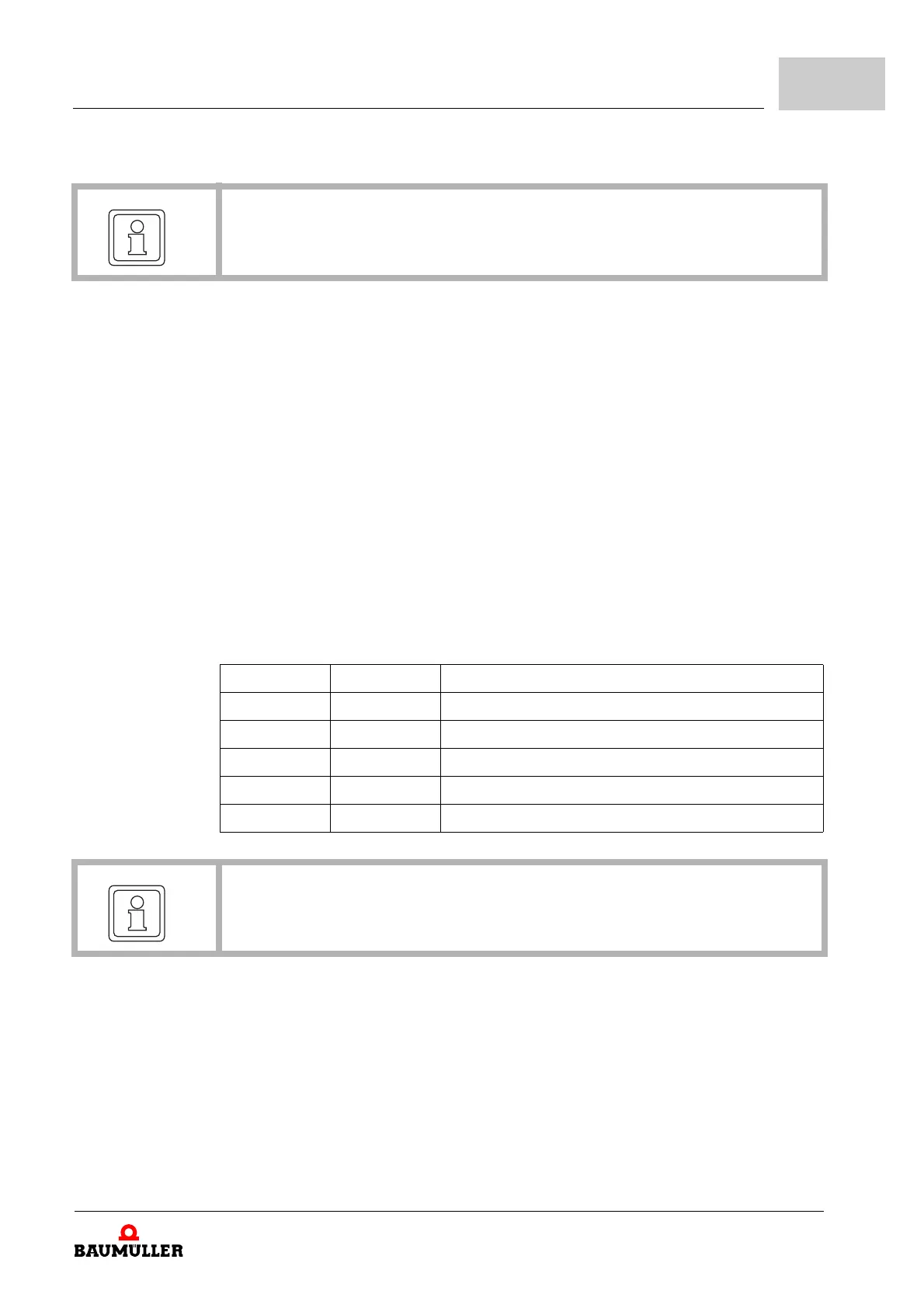
The structure of the subindices for the mapping ob
jects 0x1600 and 0x1A00 is as follows:
Byte offset Name
0 ... 1 Index Index of the object to be mapped
2 Subindex Subindex of the object to be mapped
3 Reserved
4 ... 5 Offset Offset related to start of PDO payload (Bit count)
6 ... 7 Length Length of the object to be mapped (Bit count)
NOTE!
On setting the mapping in the mapping parameters (0x1600, 0x1A00), it is necessary
to describe the respective subindex 0x00 with the correct number of mapped objects.
Set values: The permissible cyclical set values are marked
in a table with the column ’PDO mapping’
as ’RX’, see table ZB.2
6000 object numbers (device profile DSP 402)– from page 48.
The manufacturer-specific parameters (four th
ousands objects) must be checked up in
the parameter manual b maXX 4000 (5.03039), chapter 7.1.4 attributes.
Description