29
INSTALLER Section (en)
7729106 (02-05/19)
11. GAS VALVE AND ELECTRONIC BOARD
11.1 GASCONVERSION
The Technical Assistance Service can convert this boiler to natural gas (G20) or LPG (G31). Carry out the following operations:
1) replacement of the nozzle unit in the main burner;
2) parameterise the electronic board;
3) mechanically calibrate the gas valve pressure regulator;
4) nal checks.
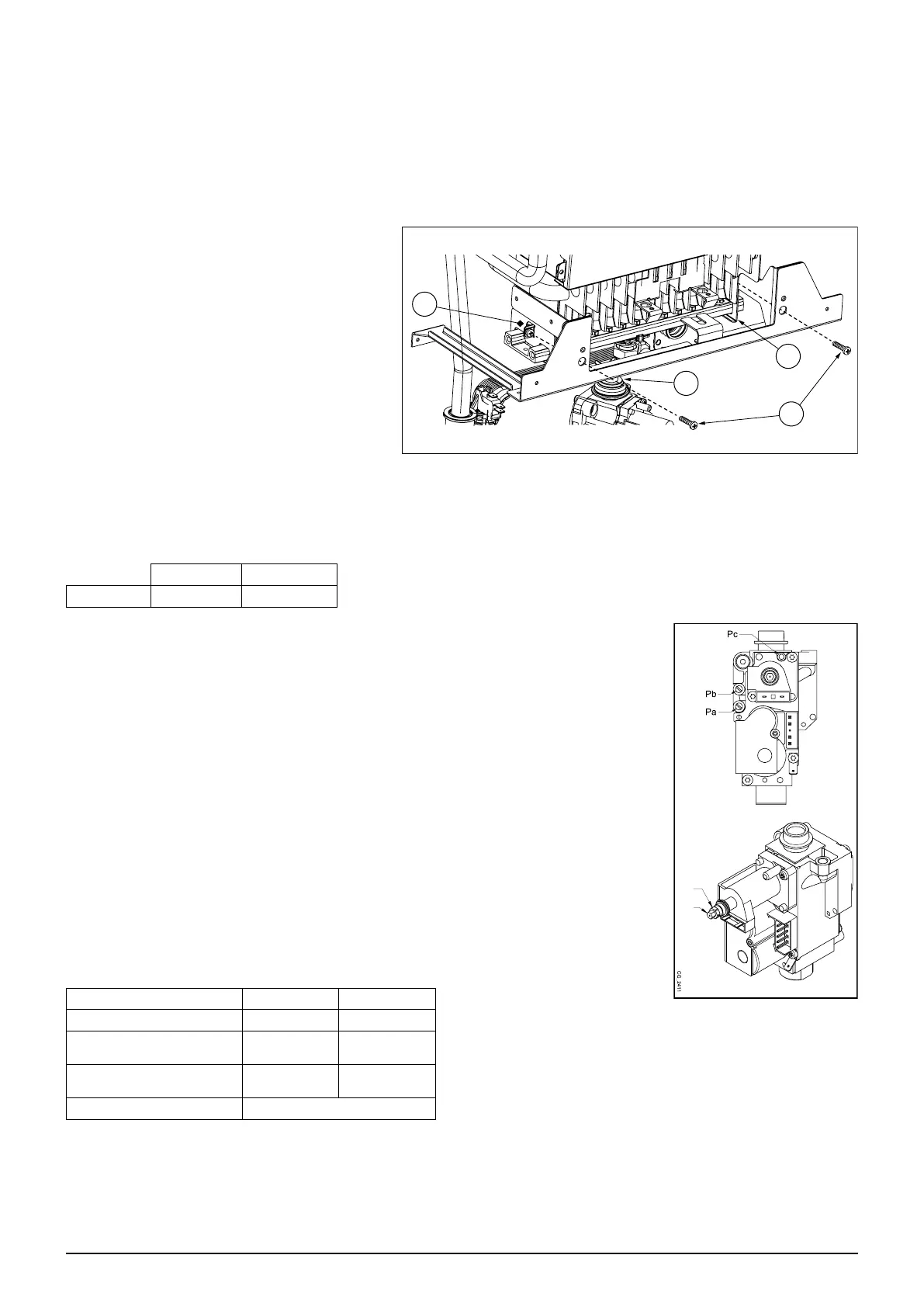
1) Replacement of the nozzle unit in the main burner
• Disconnect the boiler from the power supply;
• close the gas inlet valve;
• remove the front panel of the boiler;
• remove the gas valve/nozzle unit connection pipe
A;
• unscrew the 2 screws B securing the 2 brackets C
to the burners and move them sideways;
• remove the nozzle unit from the bottom;
• replace the nozzle unit (check the diameter of the
nozzles based on the gas used - see the nozzles-
burner pressure table);
• for the reassembly follow the same procedure in
the reverse order, making sure that there are no
gas leaks.
WARNING: do not unscrew the nozzles from the nozzle unit. The whole nozzle unit must be replaced.
2) Parameterise the electronic board
• Power the boiler;
• set the parameters (Fxx) with the values indicated in the following table, depending on the gas type following the procedure
described in the SETTING PARAMETERS section.
G20 G31
F02 0 1
3) Mechanically calibrate the gas valve pressure regulator
• Connect the positive pressure test point of a pressure gauge, possibly water-operated, to the
gas valve pressure test point (Pb);
• open the gas tap and switch the boiler to the "Winter" mode;
• open a hot water tap that can provide a ow rate of at least 10 litres a minute or make sure
there is maximum heat demand;
3a) Adjust to nominal heat output:
• remove the modulator cover;
• adjust the tube brass screw (a) until the pressure values shown in the nozzles-burner pressure
table correspond to the nominal heat output;
• make sure that the dynamic inlet pressure of the boiler, measured at the gas valve pressure
test point (Pa) is correct, as indicated in the TECHNICAL SPECIFICATIONS section.
3b) Adjust to reduced heat output:
• disconnect the modulator power cable and adjust the screw (b) until the pressure values
corresponding to the reduced power indicated in the burner nozzles-burner pressure table are
obtained;
• reconnect the wire;
• mount the modulator cover and seal.
Nozzles-burner pressure table
Gas type G20 G31
Nozzles diameter (mm) 0,85 0,52
Burner pressure (mbar*)
REDUCED HEAT OUTPUT
2,5 5,8
Burner pressure (mbar*)
RATED HEAT OUTPUT
13,3 30,8
N° nozzles 26
* 1 mbar = 10,197 mm H
2
O
4) Final checks
• Note down the conversion on the boiler data label, specifying the type of gas and indicating that calibration was performed.
7730973
A
B
C
C
(b)
(a)
 Loading...