7729106 (02-05/19) 30
INSTALLER Section (en)
11.2 REPLACING THE GAS VALVE
When replacing the gas valve, perform the following operations:
• switch o the boiler;
• close the gas inlet valve;
• replace the gas valve;
• open the gas inlet valve and make sure there are no gas leaks;
• perform the operations described in points 3 of the GAS CONVERSION section.
11.3 GAS VALVE CALIBRATION
To calibrate the gas valve, perform the operations described in points 3 of the GAS CONVERSION section.
11.4 REPLACING THE ELECTRONIC BOARD
When replacing the electronic board, perform the following operations:
• disconnect the boiler from the mains power supply.
• close the gas inlet valve;
• remove the front panel of the boiler;
• replace the electronic board;
• power the boiler;
• “the display shows “E98”;
• set parameters F01, F02, F03 and F12 as described in the SETTING PARAMETERS section according to the boiler model
indicated on the data label.
11.5 REPLACING THE ELECTRONIC BOARD + GAS VALVE
When replacing the electronic board and the gas valve at the same time, perform the following operations:
• disconnect the boiler from the mains power supply.
• close the gas inlet valve;
• remove the front panel of the boiler;
• replace the electronic board;
• replace the gas valve;
• open the gas inlet valve and make sure there are no gas leaks;
• power the boiler;
• “the display shows “E98”;
• set parameters F01, F02, F03 and F12 as described in the SETTING PARAMETERS section according to the boiler model
indicated on the data label.
• perform the operations described in points 3 of the GAS CONVERSION section.
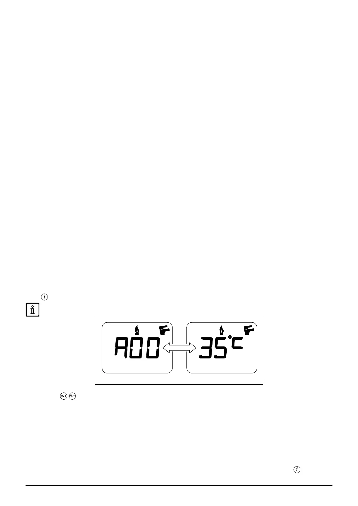
12. VISUALISATION OF PARAMETERS ON THE DISPLAY ("INFO" FUNCTION)
Press for at least 6 seconds to display information concerning boiler operation.
When the “INFO” function is enabled, the message “A00” alternating with the boiler delivery temperature, is shown on the
display:
CG_1808
Press buttons to display the following information:
A00: current heating delivery temperature (°C);
A01: current DHW temperature (°C);
A02: current external temperature (°C) (with external sensor connected);
A03: current fumes temperature (°C);
A04: instantaneous (%) value of the gas valve control signal;
A05: power range (%) (MAX CH);
A06: heating setpoint temperature (°C);
A07: DHW temperature setpoint (°C);
A08: last error that occurred in the boiler;
A09: not used;
A10: not used.
This function remains active for 3 minutes. It is possible to interrupt the “INFO” function in advance by pressing or turning o
the power to the boiler.
 Loading...