35
INSTALLER Section (en)
7729106 (02-05/19)
17. ANNUAL SERVICING
If the boiler was operating, wait for the combustion chamber and pipes to cool down.
Before commencing any maintenance operations, make sure the boiler is disconnected from the power supply. Afterwards,
move the knobs and/or operating parameters of the boiler to their original positions.
Do not clean the boiler with abrasive, aggressive and/or easily ammable substances (such as petrol, acetone, etc.).
To optimise boiler eciency, carry out the following annual controls:
• Check the appearance and airtightness of the gaskets of the gas and combustion circuits. Replace any worn seals with new
original spares;
• Check the state and correct position of the ignition and ame-sensing electrodes;
• Check the state of the burner and make sure it is rmly xed;
• Check for any impurities inside the combustion chamber. Use a vacuum cleaner to do this;
• Check the gas valve is correctly calibrated;
• Check the pressure of the heating system;
• Check the pressure of the expansion vessel;
• Make sure the ue and air ducts are unobstructed;
17.1 HYDRAULIC UNIT
For special areas, where the water is harder than 20 °F (1 °F = 10 mg calcium carbonate per litre of water), install, on the cold
water inlet, a polyphosphate dispenser or an equivalent treatment system, compliant with current regulations.
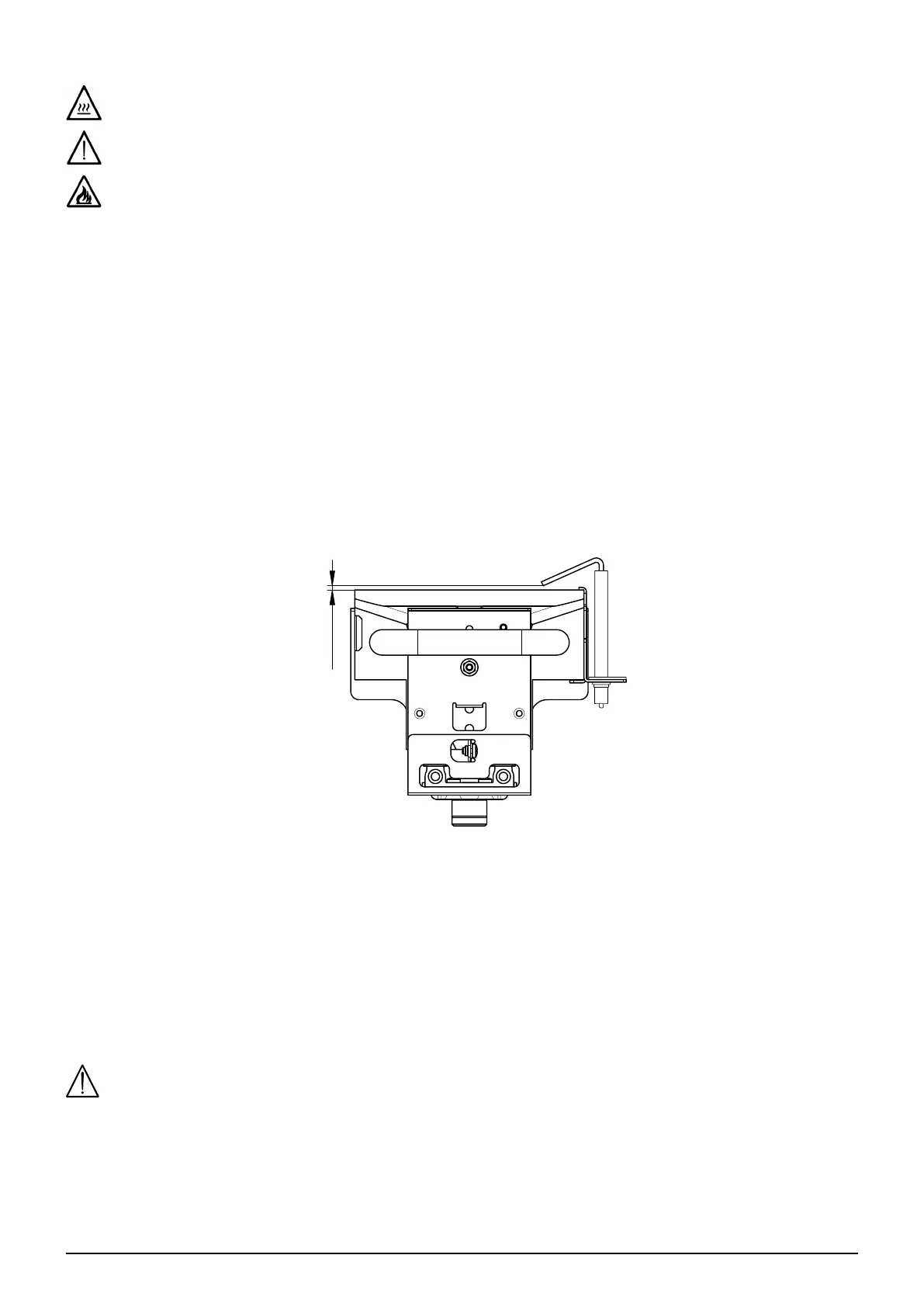
17.2 POSITIONING THE ELECTRODE
3
0,5
7720828
17.3 CLEANING THE FILTERS
The DHW lter is housed in a special removable cartridge and is positioned on the cold water inlet (E) (see gure at the end of the
manual in "SECTION" F). To clean the lter, proceed as described below:
• switch o the boiler;
• shut the DHW inlet tap;
• remove the clip (1-E) from the lter as illustrated in the gure and take out the cartridge (2-E) containing the lter, taking care
not to apply excessive force;
• eliminate any impurities and deposits from the lter;
• reposition the lter in the cartridge and put it back into its housing, securing it with the clip.
Remove the scale from the housing and relative NTC sensor tted on the DHW circuit (D).
When replacing and/or cleaning the O-rings on the hydraulic assembly, only use Molykote 111 as a lubricant, not oil or
grease.

 Loading...