8.13GeneralFittingNotes
NOTE:Thefluesystemmayonlybeinstalledasdescribedinthissection
1.Cutaholeintheexternalwallwhichtheconcentricflueassemblywillpassthrough.Theholeshouldallowthefluetofallbacktotheboileratanangleof1.5°to3°.
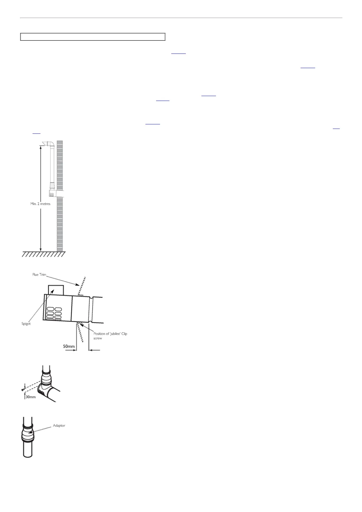
2.Whencompletedtheterminalmustbeatleast2metresabovegroundlevel(Fig.21g).
3.Measureandcuttosizetheconcentricassemblyandanyextensionsthatarebeingused.
4.Inserttheconcentricassemblythroughtheholefromoutsidethebuilding.
5.Ifrequired,theflexiblefluetrimshouldbefittedpriortothisasitcannotbefittedafter.Usethelarge'Jubilee'cliptosecurethetrimtotheflue(SeeFig.21h,trimshown
dotted),withthescrewpartoftheclipatthebottom.
6.Connectanyextensionsorelbowsthatarebeingusedtotheconcentricassembly.Engagetheextension,elboworconcentricassemblyintheboilerflueelbow.Fitthe
boilerflueelbowtotheboileradaptor.
7.Ensurethattheconcentricassemblyandanyextensionsfallbacktotheboileratanangleofatleast1.5°andthattheexternalairinletistothebottom.
8.Usesuitablebracketstosupporttheconcentricassemblyandanyextensions,andmakegoodinsideandoutside.
9.The60Øexhaustcannowbefitted.Slidetheadaptorovertheplainendofthe60Øexhaust(Fig.21k)andengagetheexhaustintheterminal.Slidetheadaptordownover
thespigot.Markanddrilltheadaptor,usinga2mmbit,asshowninFig.21j.Securetheadaptortothespigotusingoneofthescrewssupplied.
10.Ifitisnecessarytoshortenthe60Øexhaustoranyoftheextensions,theexcessmaterialmustbecutfromtheplainendofthepipe.
11.Determinethepositionofthe60Øexhaustandmarkonthewallasuitablepositionforthesupportbracket.Ifextensionsarebeingused,asupportbracketissuppliedin
eachkit.
12.Drillthewall,andfitthebracket(s)usingtheplugandscrewprovided.
13.Markanddrillthe60Øexhaust,usinga2mmbit,asshowninFig.21L.Completetheinstallationofthe60Øexhaust,securinginthebrackets.
14.Fitthe93°elbow/plumeoutletandsecurewiththetworemainingscrewssupplied.Ensuretheplumeoutletisatleast45°tothewallandthatthe'peak'isuppermost(Fig.
21m).
Fig.21g
Fig.21h
Fig.21j
Fig.21k

 Loading...