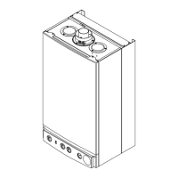
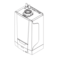
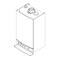
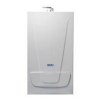
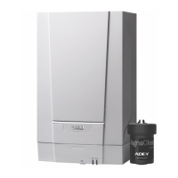
Fig.45
10.16Outsidesensorunitinstallationprocedure
1.Outsidesensorlocation:TheoutsidesensorcartonisillustratedwithSuitablelocationsandadvisesagainstlocationswhicharelikelytogivepoor/falsereadings.
2.Avoidsouthfacingwalls;preferablychooseawesttonorthfacinglocation.
3.Theidealheightforthesensorisatapproximatelyhalftheheightofthelivingspaceofthedwellingandnolessthan2.5mofftheground.
4.Avoidlocatingthesensorclosetotheflueterminalwheretheflueplumecouldheatthesensorandcausetheappliancetoswitchoffprematurely.
5.Twocore"bellwire"issuitable.
6.Whencorrectlyconnectedandoncethe'Savesensor'procedurehasbeendone(SeeSection11.4),theoutsidetemperatureandiconwillbedisplayontheTHINK
Controller(SeeSection10.12andFig42).
page49
10.17WirelessInstallation
1.IfawirelesssystemisbeinginstalledthencommunicationmustbeestablishbetweenthevariousRFcomponentsandthespecialRF5LEDReceiverwhichcontainsthe
transceiverfortheappliance.Eachkitasoutlinedinsection6.7includesinstallationinstructions.Anoverviewisgivenbelow:
2.Inthewireless5LEDkit(partno.720026201)thewireless5LEDReceiverandthecradlearepreboundbutsubsequentcradlesholdingTHINKControllerforsecond
heatingcircuitsmustbeconnectedor'bound'tothe5LEDtransceiver.
3.TheavailableRFcomponenttransmittersare:
ThecradleenablesdirectconnectionwiththeTHINKController.
Theoutsidesensortransmitter.
TherepeaterunitenablescomponentstobepositionedinotherwisedeadareastotheRF5LEDReceiver.Therepeaterunitrequiresamainssupply.
4.ObservethesameconsiderationsforlocatingthewirelessTHINKControllerasthewiredroomsensor.
5.Tobindtheunitstogetherusethefollowingprocedures.
6.EachTHINKControllermustbeallocatedtothecorrectheatcircuiti.e.roomunit1/roomunit2/operatorunitasdescribedinSection10.13and11.3paragraphk,thiscan
bedoneontheapplianceorlaterwhenintheRFcradle.
7.SwitchtheapplianceonandinserttheRF5LEDReceiverintoeithertheapplianceoranoffappliancewiredcradle.
8.IftheRFCradleandRF5LEDReceivercameboxedtogetherthentheywillbeprebound.Insertthe3xAAbatteriesintotheRFcradleandinserttheTHINKController,'data
update'willshowandthenthepercentageprogresswillshowiftheTHINKControllerisnewtotheappliance.Afterashortwhile'Operatorunitready'thenthestandard
screenwillappear.TheTHINKControllercannowbeusedasanRFprogrammableroomsensor.
9.IfError83appearsmovetheTHINKControllerintheRFcradleclosertotheRF5LEDReceiver.Ifdistance/lineofsightisnottheproblemtheRFcomponentswillneed
tobeconnectedor'bound'togetherusingthefollowingprocedure:
10.PressandholdtheresetbuttonontheRF5LEDReceiveraround10secondsuntilthesecondandfourthLEDSarelit.
11.Pressthemenubuttontoentertheusermenuandthenpressandholdtheeasymenuandmenubuttonsuntiltheotheraccesslevelsappear.Scrolldowntothe
commissioningoptionandselectbypressingtheSelectorButton.Scrolldowntothewirelessoptionsandselecttoenterthislistasshownopposite.
12.Selectparameter120,scrollto'yes'.'Wait'willappearuntiltheunitisbound.Aseachunitisboundtheywillappearinthelistaboveasbeing'inoperation'.Ifaunitdoes
notappear,moveittoadifferentlocationandthenchooseandconfirmtestmode.Thiswillinitiateaseriesof24testsignalswhichareshownalongthetopofthedisplay
andsentbackandshownonalineunderneath.Movetheunittoalocationwhereatleast20ofthesesignalsareechoedback.Iffewornosignalsarereceiveditwillbe
necessarytousearepeaterunittorelaythesignal.
NOTE:TheTHINKControllerrefreshratewillbeslowerthanwhenitismounteddirectlyontheapplianceorinawiredcradle.
IMPORTANT:Beforerunningtheapplianceensureparameter5700hasbeensetaccordingtothetypeofsysteminstalled.
Seesections10.4to10.11forsystemtypesandsection11.3.kforthechangeprocedure.
Wirelessmenu
Line2 Line3 Parameter
1. Binding Trigger? no/yes 120
2. Testmode Trigger? no/yes 121
3. RoomUnit1 Deletedevice? missing/inoperation 130
4. RoomUnit2 Deletedevice? missing/inoperation 131
5. RoomUnit3 Deletedevice? missing/inoperation 132
6. Outsidesensor Deletedevice? missing/inoperation 133
7. Repeaterunit Deletedevice? missing/inoperation 134
8. OperatorUnit1 Deletedevice? missing/inoperation 135
9. Deletealldevices no/yes 140
page50
11.0Commissioning
11.1PreliminaryElectricalChecks
1.ReferenceshouldbemadetoBS:EN12828,14336and5449Section5whencommissioningtheboiler.
2.Priortocommissioningtheboilerpreliminaryelectricalsystemchecksshouldbecarriedout.
3.Removetheoutercase,thebottompanelandlowerthecontroltraytogainaccesstotheelectricalconnections(seesection10.1).
4.Theseshouldbeperformedusingasuitablemeter,andincludechecksforEarthContinuity,ResistancetoEarth,EarthLoopImpedance,ShortCircuitandPolarity.
5.Atthetimeofcommissioning,completeallrelevantsectionsoftheBenchmarkChecklistattherearofthispublication.
11.2CommissioningtheBoiler
NOTE:Thetransitbrackets3offmustonlyberemovedjustbeforecommissioningtheappliance.
1.Theengineisheldsecurelyfortransitby3brackets(Figs.48&49).Toensurethatall3bracketsareremovedbeforefiringtheappliance,twosecuritymeasuresmustbe
overcome:
a)Firstlyall3bracketsarewiredtogether.Removethebottom(leftandrighthand)bracketsfirst(Fig.49)byremovingthescrewsfromunderneaththeengineandthenundothe
M6screwssecuringthebracketstothebackoftheappliance.Disengagethebracketsandwithdraw.
RemovethetopcentrebracketbyremovingthethreeM5screws(8mmspanner)(Fig.48).
NOTE:Pleaseretainthescrewsandbracketsincaseresitingtheapplianceisnecessary.
Thecenterbracketshouldalsoberefittedtoprotecttheengineheadduringservicing.
 Loading...
