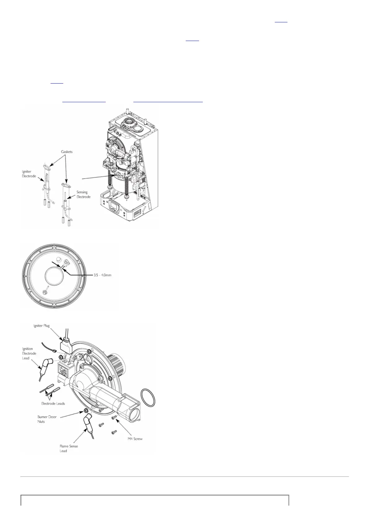
4.Examineandcleanorreplacetheelectrodesasnecessary.Thesparkgapshouldbe3.54.0mm,adjusttheearthpinifrequired(Fig.54).
5.Alwaysusethenewgasketsprovidewhenreplacingtheelectrodes.
6.Replaceinthereverseorder.
SupplementaryBurnerandHeatExchanger,IgniterandFlameSensingElectrodes(Fig.55)
1.DetachthesupplementaryIgniterplug.
2.Detachtheflamesenseleadfromthewiringharness.
3.RemovethefourM5screwsattherightofthesupplementaryairgasmanifold.
4.Undothesixnutsaroundtheburnerdoorperimeternotingthepositionoftheearthlead.
5.Carefullywithdrawtheburnerdoorandmanifold.
6.Cleananydebrisformtheheatexchangerandcheckthatthegapsbetweenthetubesareclear.
7.Inspecttheburner,insulationandtheelectrodes,cleanorreplaceifnecessary.Resettheelectrodesparkgaptobetween3.54.0mmbyadjustingtheearthpinif
required(Fig.54).
8.Ifitisnecessarytoreplaceelectrodesalwaysusethegasketsprovided.
9.Reassembleinthereverseorderrememberingtoattachtheearthwire.
CompletetherelevantServiceIntervalRecordsectionoftheBenchmarkCommissioningChecklistattherearofthispublicationandthenhanditbacktotheuser.
Fig.53
Fig.54
Fig.55
page60
14.0ChangingComponents
IMPORTANT:Whenchangingcomponentsensurethatboththegasandelectricalsuppliestotheboilerareisolatedbeforeanyworkisstarted.

 Loading...