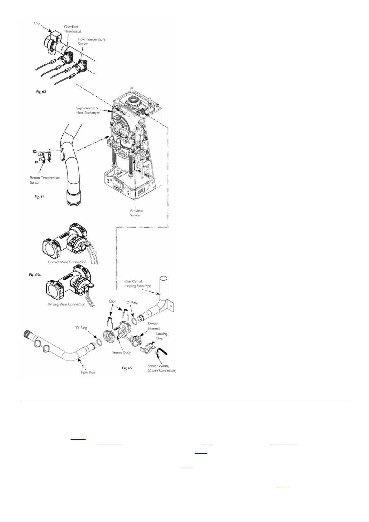
Fig.63Fig.65
page64
14.15Supplementaryheatexchanger
Beforestartingthisprocedureensuretheappliancehascooledsufficientlytoallowhandlingoftheheatexchanger.Ifitisnotintendedtoreplacetheheatexchangerensurethat
aservicekitisonhandforreassembling.
1.Isolatetheappliancefromallservices.
2.Usethedrainpoint(Fig.66a)toremovethesystemwaterfromtheappliance.
3.Removetheassembliesshowninsections14.4,theburnerdoorassemblyasdescribedin14.10andthewaterflowswitchasinsection14.14.Disconnecttheflueand
removetheflueconnectorassemblybyundoingthefourselftappingscrews.
4.Releasetheflowpipefromthesupplementaryheatexchangerremovethespringclip(Fig.67).Undothefittingatthetopofthedrainvalve.Loosenthecompression
fittingsontheflowandreturnpipestotheapplianceandthenswingthepipesawayfromthesupplementaryheatexchanger.
5.Usinga5mmhexdrive,undoandremovetheclampingcollarbetweenthesupplementaryheatexchangerandtheengineburner.
6.Disconnectthecondensedraintubeatthebottombackoftheheatexchanger(Fig.67).
7.Thesupplementaryheatexchangerwillstillcontainsystemwatersocareisneededtobetakenwhenitisliftedfromtheappliance.Ensurethattheelectricalconnections
andthePCBareaareprotectedfromanypossiblespillages.Carefullylifttheheatexchangertotherightoftheapplianceandpullforwards.Ensurethatthedrainextension
doesnotfoultheengineburnerinsulation.Therewillstillbesystemwaterintheheatexchangersocareneedstotakenwhenhandlingtoavoidaccidentalspillages.
8.Removethesupplementaryreturnpipefromthesupplementaryheatexchangerbyremovingthetwoscrewsandtheretainingplate(Fig.67).
9.Reassembleinthereverseorder.Useanewengineburner/supplementarygasketandOrings.Akitofpartsisprovidedwithanewheatexchanger.

 Loading...