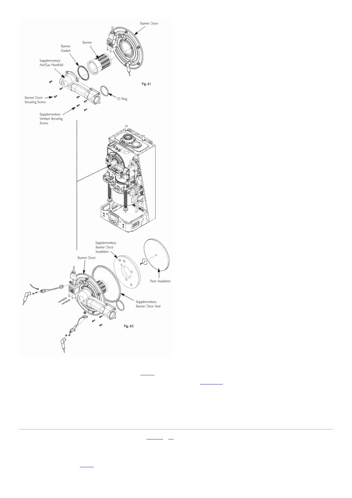
Fig.61&Fig.62
14.10SupplementaryBurner/HeatExchangerInsulation(Fig.62)
1.Removetheelectrodeleads,notingtheirpositions.Alsoremovetheelectrodesasdescribedinsection14.2.
2.Undothescrewssecuringthemanifoldtotheventuriandthenutsholdingtheburnerdoortotheheatexchanger.Drawtheassemblyawayfromtheheatexchanger.
3.Inspectandremovetheburnerdoorinsulation.
4.Fitthenewinsulationcarefullyovertheburnerandalignitwiththeslotsfortheelectrodes.
5.Inspecttherearinsulation,replaceifcrackedorbroken.Itisretainedbyasmallscrewandalargewasher.Undothescrewcarefully,removetheinsulationandfitnew
insulation.Cleananydebrisfromtheheatexchangerpreferablywithavacuumcleaner.
6.Examinetheburnerdoorsealandreplaceifnecessary.
7.Reassembleinreverseorder.
page63
14.11CentralHeatingFlow&ReturnTemperatureSensors(Figs.63&64)
1.Disconnecttheconnections.
2.Removetheretainingscrews
3.Fitnewsensorandreassembleinthereverseorder.
14.12OverheatThermostat(Fig.63)
1.Pulltheconnectorsoffthethermostat.

 Loading...