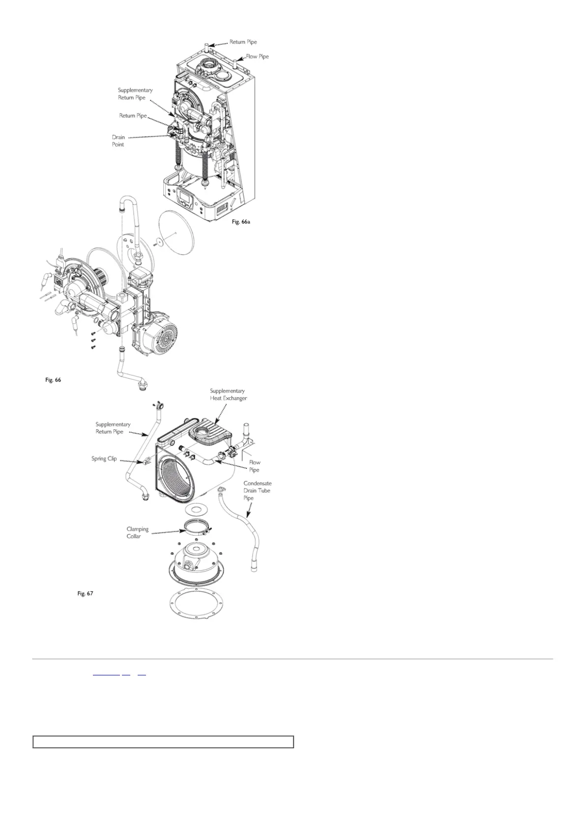
Fig.66aFig.67
page65
14.16PCBMain(Figs.68,69&70)
1.Undothe4screwsfromthebottomcoverandremovethecover.
2.Undothe2screwssecuringthecontroltray,pulltheassemblyforwardandcarefullyallowtheassemblytodropdown.
3.Removethe2screwssecuringthecontrolcoveratthelefthandcorners.LiftatthelefthandsideanddisengagefromtheG83/24Vpowersupplyhousingontheright.
4.Carefullyremovetheconnections.Therearethreeconnectionstoeachburnercontrolunit(BCU).Fourconnectionsonthemainboardandfifteenaroundtheedge.
5.Removethescrewatthebacklefthandcorner.PushthePCB/coverassemblyback(approx10mm)andliftouttheassembly.
6.Reassembleinthereverseorder.
NOTE:Theconnectionsare"justified"sothatitisimpossibletoconnectupincorrectly.

 Loading...