3.2.3 servo circuit
3.2.3.1:
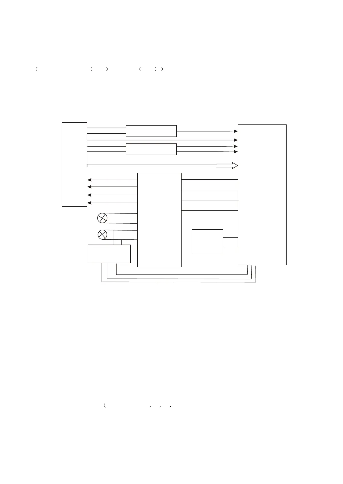
1.Servo system of this player adopts SANYO HD62 chip and MTK decode scheme
MT1389S+FLASH 16M +SDRAM 64M . And servo circuit is mainly composed by front signal
processing and digital servo processing IC MT1389 and driving circuit AM5888. MT1389 is also main part
of decode circuit. Block diagram of servo circuit is shown in figure
FOSO
FMSO
TRSO
DMSO
A B C D E F RFO
IOA
LDO2
LDO2
MD11
Switch Circuit
APC circuit
Main axis control
detect circuit
Main axis electric motor
Feed electric motor
XS301
AM5888
MT1389
Tray oper/close
circuit
TK-
TK+
FC+
FC-
SL+
SL-
SP-
SP+
1
23
4
26
15
16
14
13
17
18
12
11
Figure 3.2.3.1 Block diagram of servo circuit
2. Working principle:
When power on or the tray is in right position, pick-up of loader starts to reset. When pick-up is in
right position, detect switch would give a signal to MT1389, which begins to output focus, main axis and
light-emitting signals. Player starts to rotate pick-up , recognize disc information and judges whether it is
CD or DVD according to disc information. So that IOA pin can output level and make disc switch circuit
and pick-up PD IC perform corresponding control motions. At the same time, MT1389 controls circuit
through laser power to adjust laser output power.
When loader reads disc information, A, B, C, D, E and F signals would form to MT1389 through
photo electric conversion DVD only has A B C D signals). These signals separately input through
pin 6~14, pin 17 and 18 together with RF signal. After amplified by pre-amplifier in MT1389, signals in
MT1389 divides into two parts: one part produces servo error signal through sum amplifying and
subtract circuit inside MT1389. After processed by digital signal circuit, those signals form
- 21 -