2. Working principle: To prolong the service life of electric machine and decrease the influence of
start-up concussion current to the machine, when there is disc in, the development personnel design the
main axis electric machine in running state always. Even though “STOP” button is pressed, disc will not
stop running immediately. Thus when pressing “OPEN” button, a braking signal is required to make the
main axis electric machine stop running to fulfill the completion of opening disc tray in a short period.
In the course of playback, press “OPEN" button and main axis drive signal disappears. For the
reason of inertia, the main axis electric machine is still in running state, and now the induced voltage
achieved by the induced electromotive force which is generated by electric machine's running on
sampling resistor R91 and R92 outputs from pin 33 through resistor R89, R90 and pin 34, 35 of MT1389
after being processed inside MT1389 and magnified; after A/D conversion and the corresponding
processing inside MT1389, an instant electric machine reversal braking signal is outputted from pin 36
of MT1389 to make the main axis electric machine decrease speed. When MT1389 detects the disc
stops running, disc tray will open to ensure that disc will not run when disc tray opens.
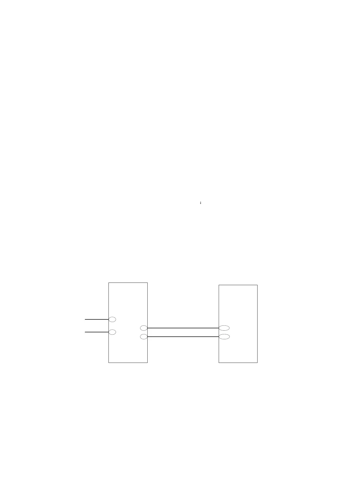
3.2.6 Tray open/close driving circuit
1. Tray open/close driving circuit is shown in figure 3.2.6.1
2. Working principle: When machine reads disc normally, pin 6, 7, 9 and 10 of AM5888S are all 0V.
Pin 6 inputs high level when press tray open button. Pin 10 LOAD+ outputs high level and electric motor
rotates positively, tray open execution is performed. When close the tray, pin 7 inputs high level; pin9
LOAD- outputs high level to pin9 through electric motor and forms loop; electric motor rotates
negatively; tray close execution is performed. When tray is closed to right position, all lead feet are low
level.
LOAD+
TRCLOSE
TROPEN
LOAD-
AM5888S
MT1389
Figure 3.2.6.1Tray open/close driving circuit diagram
10
9
6
7
38
210
3.2.7 Reset circuit
1. Reset circuit is shown as in the following figure 3.2.7.1:
- 24 -