PIN Signal Assignment PIN Signal Assignment
1 TMDS Data2+ 2 TMDS Data2 Shield
3 TMDS Data2- 4 TMDS Data1+
5 TMDS Data1 Shield 6 TMDS Data1-
7 TMDS Data0 8 TMDS Data0 Shield
9 TMDS Data0- 10 TMDS Clock+
11 TMDS Clock Shield 12 TMDS Clock-
13 CEC 14 Reserved (N.C. on device)
15 SCL 16 SDA
17 DDC/CEC Ground 18 +5V Power
19 Hot Plug Detect
3 Definition of HDMI Type A jack is shown as follows:
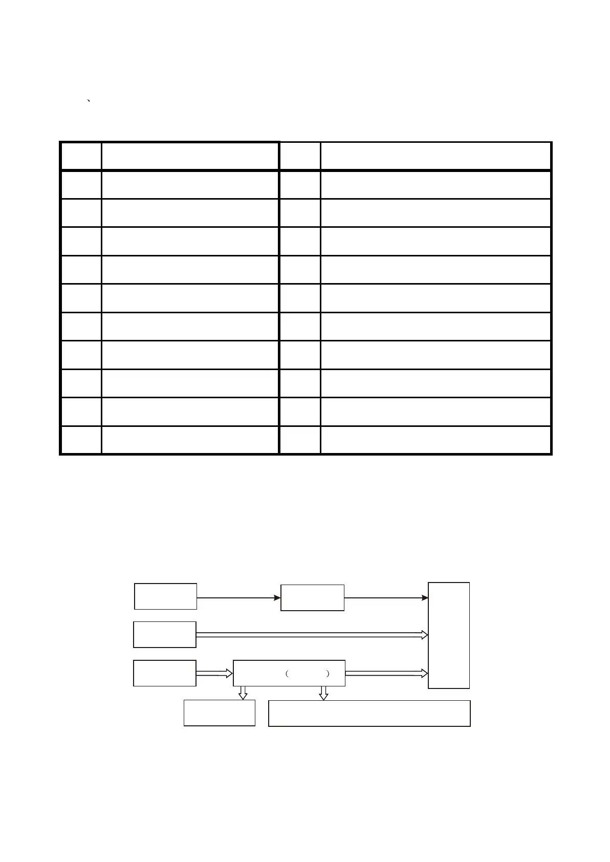
3.2.12 Control panel components
1. Control panel components block diagram is shown as the following figure 3.2.12.1:
Remote
controller
IR receiver
Digital
potentiometer
Decode board
Button
VFD screen
CLK, STB, SDA
Drive light emission diode
VD105, VD106, VD107
Figure 3.2.12.1 Control panel components block diagram
N101 TP6317
- 29 -