2. Working principle: panel is mainly composed of VFD screen, drive chip TP6317, remote
controller IR receiver, digital potentiometer, button and indicator light.
VFD is a vacuum fluorescence display screen and the working principle is the same with that of
CRT TV set, that is, emit light and display through electron bombarding fluorescent powder. Pin 1, 2, 34
and 35 of VFD are filament power supply pin, GRID1~GRID8 is segment control equal to grid, which
speeds up electro emission and is responsible for display selection within reticular scope in display
screen. SEG1~SEG16 is bit control connected to single character with fluorescent powder on it. When
electro is bombarding it, it emits light and displays character or strokes.
The function of N101 (TP6317) is to drive display to display the corresponding state after
processing data signal sent from decode board, meanwhile scan panel buttons matrix and sends it to
CPU in digital signal means after processing button information to control the player and perform the
corresponding acts.
Pin 3 of remote control IR receiver is 5V power supply pin, pin 2 grounds, and pin 1 is output pin.
After processing remote controller buttons information, remote control receiver outputs from pin 1 and
then sends to decode board directly.
Digital potentiometer is used to adjust volume, which uses the phase difference of pulse send out
from pin 1 and 3 of it to realize the adjustment of volume.
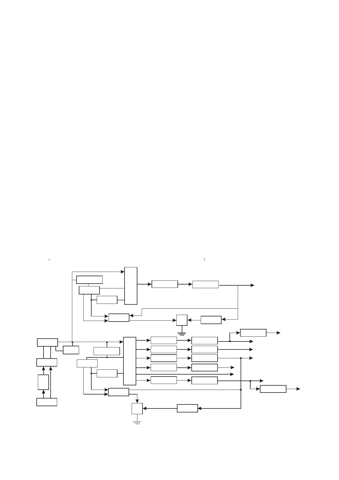
3.2.13 Power circuit
1 Block diagram of power circuit is shown in figure 3.2.13.1
Figure 3.2.13.1 Block diagram of power circuit
Tr
a
n
s
f
o
r
me
r
Rectifier
Absorb circuit
Electric
wire filter
Insu
r
a
n
c
e
t
u
b
e
Power
socket
SwitchIC
Feedback
winding
optical
coupler
TL
431
Sampling
circuit
Rectifier
Filter
+9V
D+5V
CPU5V
-21V
Rectifier
Rectifier
Rectifier
Rectifier
Filter
Filter
Filter
Filter
FL-
FL+
Voltage
stabilization circuit
-9V
NCP1200D
Filter
HOST GND
A+5V
Voltage
stabilization circuit
T
r
a
n
s
f
o
rm
e
r
Rectifier
Filter
P+28V
Absorb Circuit
SwitchIC
Feedback
Winding
Optical
coupler
TL
431
Sampling
circuit
KAIM088BTU
- 30 -