R28
10K
R35
100K
R29
10K
R36
100K
Q3
2SK3018-S
Q4
2SK3018-S
Q5
3904
IOA
AVCC
IOA
54
MT1389
XS301
18
17
7
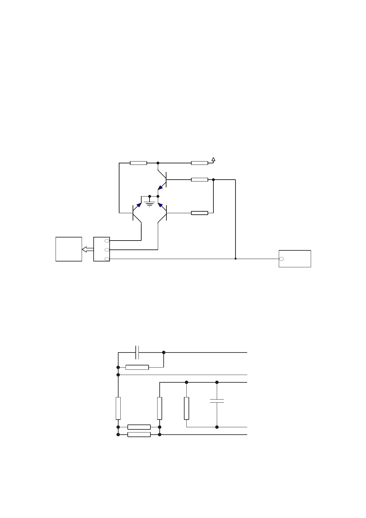
Figure 3.2.4.1 Disc identification circuit diagram
Loader
now IOA is low level input loader to make loader in the state of reading DVD, through detecting
laser power feedback signal, MT1389 analyses whether the preliminary judgment is correct (disc is
defaulted DVD). When detecting correct preliminary judgment, loader runs in the state of reading DVD;
when detecting incorrect preliminary judgment, MT1389 outputs a high voltage signal from its pin 54, Q5
and Q4 are on, Q3 is cut off, laser receiver tube inside loader selects VCD channel, now IOA is high level
input loader to make loader in the state of reading VCD. Whether the preliminarily defaulted disc is VCD
or DVD is set by MT1389 internal software.
Note: Q3 and Q4 are MOS tube.
3.2.5 Main axis braking control circuit
1. Main axis braking control circuit is shown as the following figure 3.2.5.1:
R91
1R
R90
150K
R89
150K
R84
680K
R83
680K
C90
102
OP-
OP+
V1P4
SP-
OPO
R92
1R
C91
102
Figure 3.2.5.1 Main axis braking control circuit diagram
- 23 -