2. Working principle: ordinary audio video output is same with other ordinary DVD, which make
initial process for analog audio and video signal decoded by MT1389S and send them to analog output
terminal. Digital audio output signal ASPDIF is directly sent to digital output terminal. MT1389S also can
output digital signal with HDMI standard format. HDMI standard switches 8 digit into 10 digit signal
through decoding and transmit by way of differential transmission. Signals outputted from MT1389S are
sent to HDMI jack directly to realize HDMI output. HDMI jack possesses advantages of no extra
damage, transmitting digital signal and analog signal simultaneously, enabling acceleration of
transmitting speed, no resolution limitation by SXGA, simple using, low cost, etc.
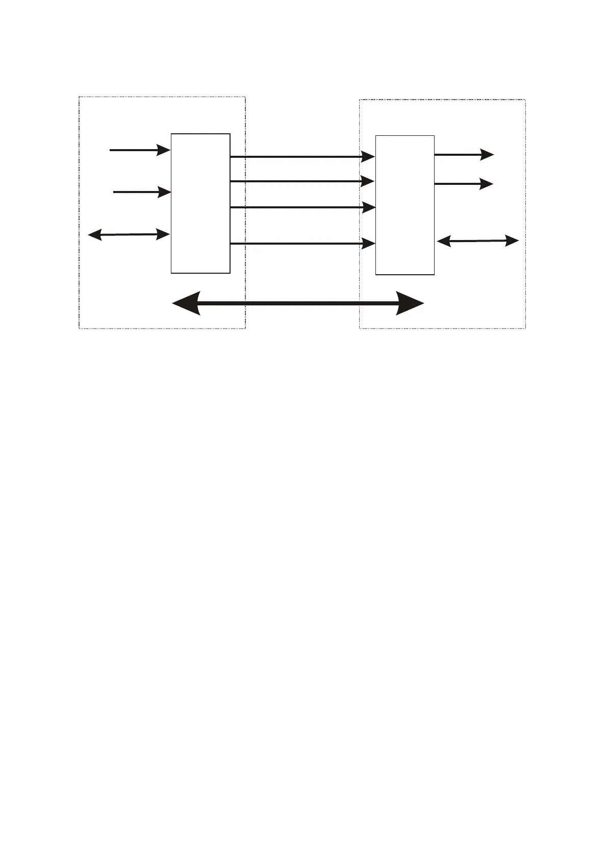
As shown in Figure 3.2.10.1 HDMI Block Diagram the HDMI cable and connectors carry four
differential pairs that make up the TMDS data and clock channels. These channels are used to carry
video, audio and auxiliary data. In addition, HDMI carries a VESA DDC channel. The DDC is used for
configuration and status exchange between a single Source and a single Sink. The optional CEC
protocol provides high-level control functions between all of the various audiovisual products in a user.s
environment.
Audio, video and auxiliary data is transmitted across the three TMDS data channels. The video
pixel clock is transmitted on the TMDS clock channel and is used by the receiver as a frequency
reference for data recovery on the three TMDS data channels.
Video data is carried as a series of 24-bit pixels on the three TMDS data channels. TMDS encoding
converts the 8 bits per channel into the 10 bit DC-balanced, transition minimized sequence which is then
transmitted serially across the pair at a rate of 10 bits per pixel clock period.
Video
HOUSE Source
HDMI Sink
Audio
Control Status
Video
Audio
Control Status
HDMI Trasmitter
HDMI Receiver
Display Data Channel
TMDS Chnanel 0
TMDS Chnanel 1
TMDS Chnanel 2
TMDS Clock Chnanel
1 HDMI Block Diagram3.2.1 .1
- 28 -