Configuration and control of the motor brake
Function description48
Version: 1.5
10.2 Control
The motor brake is generally controlled automatically via the AX5000 servo drive. For manual control, select
the service function „Manual brake control“ in the TC3 Drive Manager. This function is described later in this
chapter.
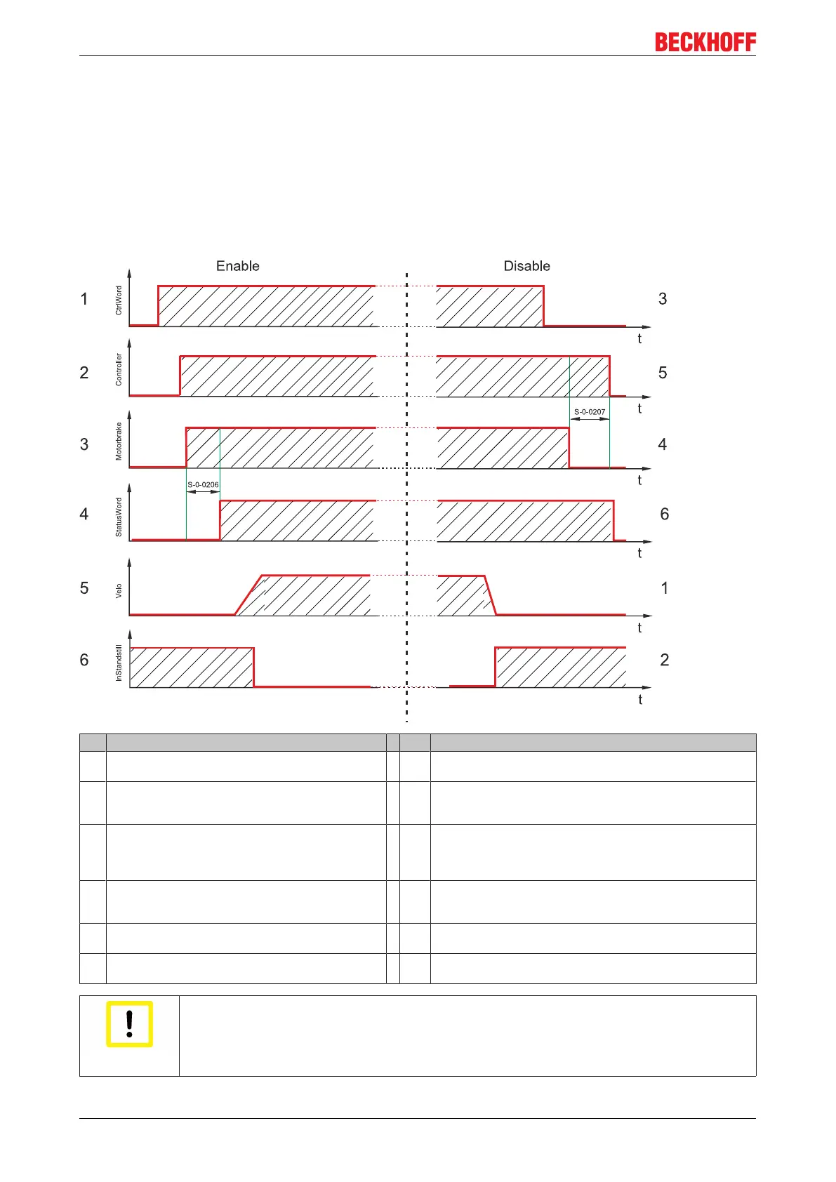
Flow diagram for the motor brake control
The following diagram shows the temporal and functional relationship between the enable signal and
opening and closing of the motor brake.
Pos Enable process description Pos Disable process description
1 The controller (NC) issues an enable request for the
holding brake to the AX5000 servo drive.
1 The target speed and the actual velocity approach standstill.
2 The control loop of the AX5000 is activated (v
target
= 0). 2 The servo drive detects the standstill of the axis with the aid of
the standstill window
(S-0-0124) and the time (P-0-0354).
3 The brake output at the servo drive is now triggered. 3 The controller (NC) disables the axis. The AX5000 servo drive
continues to control with it v
target
= 0. The axis no longer follows
the set values of the controller (NC). Bit 3 in the status word is
set to 0.
4 When the „Drive on delay time“ (S-0-0206) has
elapsed, the servo drive follows the set values of the
controller, which sets bit 3 in the status word (NC).
4 The brake output for the motor brake is now disabled.
5 The controller (NC) now specifies a travel profile for the
servo drive.
5 When the „Drive off delay time“ (S-0-0207) has elapsed, the
controller in the AX5000 is disabled.
6 The standstill flag changes its status from 1 to 0, since
the axis is now in motion.
6 The drive control is now fully disabled.
Attention
Weight counterbalance!
If the axis drops on enable, the weight counterbalance should be activated with S-0-0163.
Enter the current value required by the drive for holding the axis. For a stationary axis this
can be read in parameter S-0-0084.
 Loading...


