Digital inputs and outputs
Function description22
Version: 1.5
6 Digital inputs and outputs
The AX5000 servo drive can be used to activate various functions via digital inputs and outputs. The
functions are assigned via eight inputs (0-7); input 7 can be configured as output. The individual functions
are described in this chapter.
Note
Reference values for the digital inputs and outputs:
P-0-0251; P-0-0315; P-0-0400; P-0-0401; P-0-0402; P-0-0800
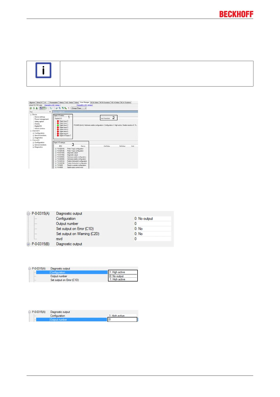
Overview of inputs and outputs with assignable functions
In the „Digital I/O status“ section (1), the TC3 Drive
Manager provides an overview of all inputs and
outputs at the AX5000 servo drive. Inputs at which no
voltage is present (low) are shown in red. Inputs at
which voltage is present (high) are shown in signal
green.
The „ActFunction“ window (2) shows whether and
where a function is active. The „Hardware enable
configuration“ is assigned to input 2.
The functions that can be assigned to the inputs and
outputs are shown in the „Digital I/O settings“ section
(3). The functions listed under (3) are described later
in this chapter.
6.1 Diagnostic output
The parameter P-0-0315 enables configuration of a diagnostic outputs at the AX5000 servo drive. For dual-
channel devices this parameter is configurable for both channels (A and B).
Configuration
Default value: 0 No output
0: No output
No diagnostic output function is selected.
1: High active
A diagnostic output function is selected.
Output number
Default value: 0 No
„Digital output 7“ can be configured as digital output with the func-
tion „Diagnostic output“ under this setting in parameter P-0-0315.
 Loading...


