Torque (Force) – Controller Structure
Function description78
Version: 1.5
18.1.1 Setpoint value calculation
Depending on the set operation mode (S-0-0032), the set value is either generated in the velocity controller
(P-0-0505) or provided directly via the torque interface (S-0-0080). The pre-control value (S-0-0081) is then
added.
18.1.2 Setpoint limiting
Setpoint limiting (see block diagram on page 1) affects the torque setpoint. Limiting is unipolar positive
(S-0-0082), unipolar negative (S-0-0083) and bipolar (S-0-0092).
18.1.3 Motor torque characteristic
The required current setpoint is determined in relation to the torque setpoint, based on the motor torque
characteristic. This current setpoint is then fed to the current controller. The actual torque for the actual
current is also based on the motor torque characteristic. When the torque controller is used with Beckhoff
motors, the data required for the motor torque characteristic are included in the electronic type plate or the
motor data files (.xeds).
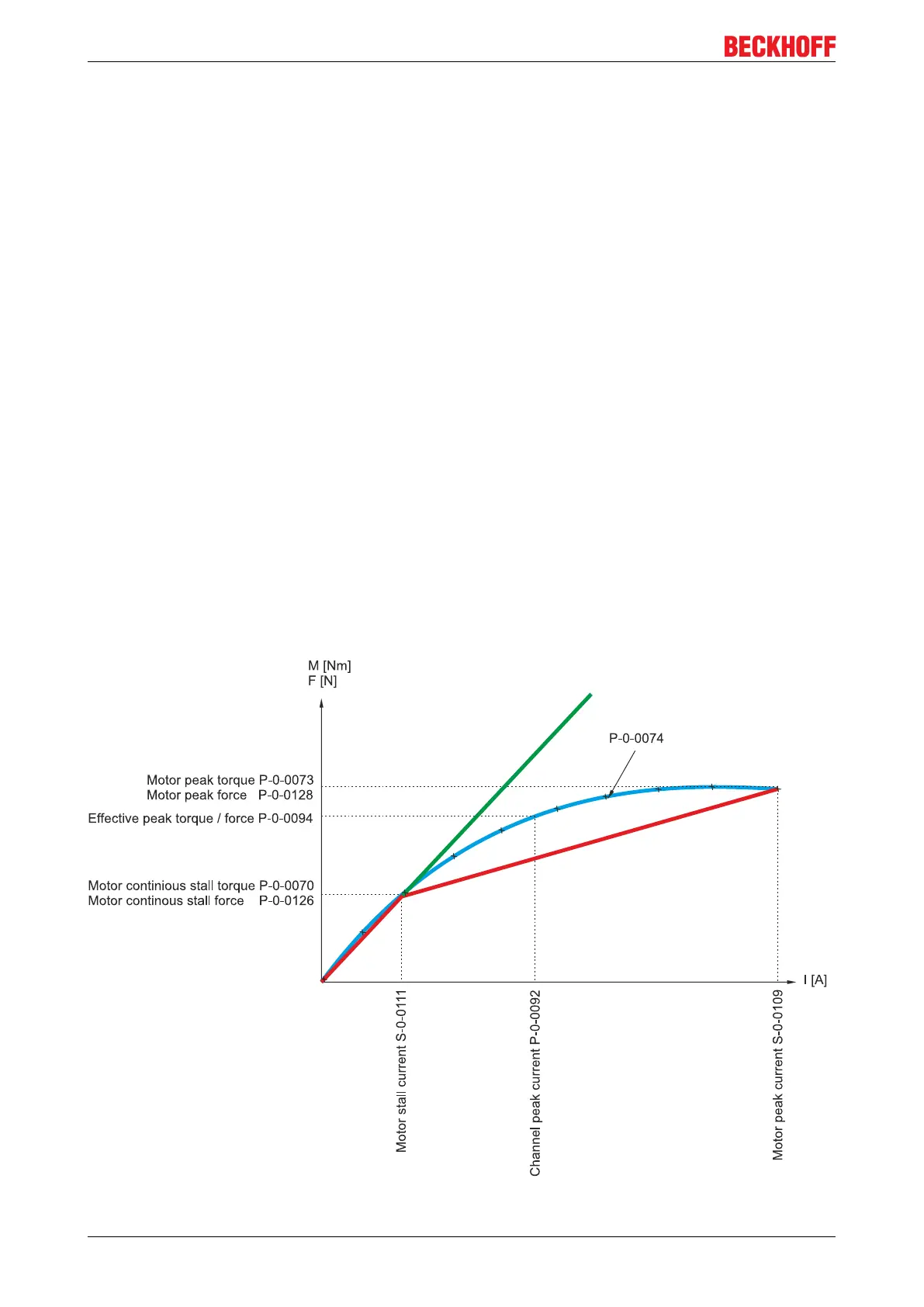
If the precise motor characteristics (saturation effects) are not available via the motor torque characteristic
(blue curve), an approximation based on the diagram shown below is used.
This approximated function (based on linear interpolation) is formed from the IDNs:
• P-0-0070, P-0-0073, S-0-0111 and S-0-0109 for rotary motors and
• P-0-0126, P-0-0128, S-0-0111 and S-0-0109 for linear motors
(see red characteristic curve).
If only the standstill torque (P-0-0070) with corresponding standstill current (S-0-0111) is available, a
conversion is performed via K
T0
(green characteristic curve).
 Loading...


