Function blocks
Function blocks for TwinSAFE logic components 125
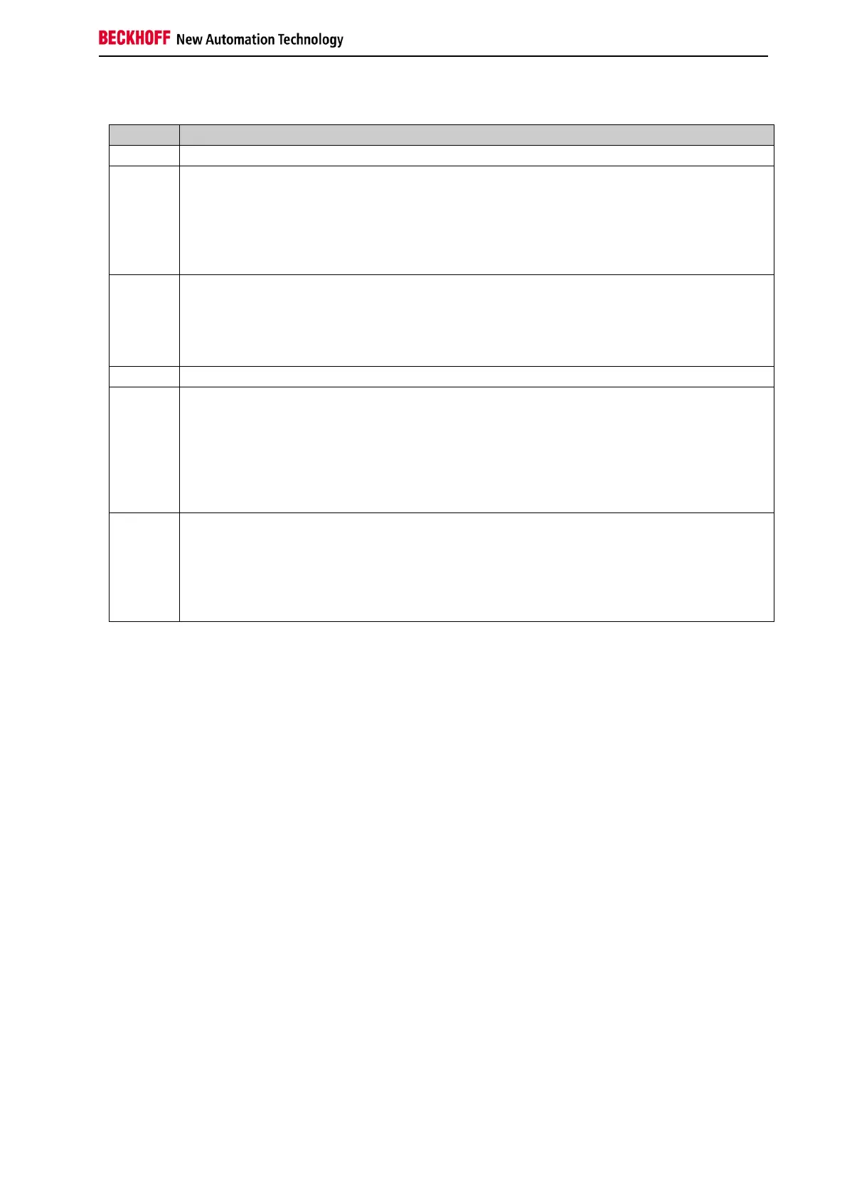
Table 3-98: State information
RUN
The FB ADD module cyclically adds the two analog inputs AnalogIn1 and AnalogIn2. If no
overflow or underflow occurs during the addition, the FB ADD module is in the RUN state.
The outputs assume the following values:
Error=0
AnalogOut = result of the addition
STOP
The FB ADD module assumes the STOP state if the input FbRun is FALSE.
The outputs assume the following values:
Error=0
AnalogOut=0
ERROR
If the FB ADD module detects an error when checking the value range of AnalogOut during
the addition, the FB ADD module switches to the ERROR state and transmits the
corresponding Diag message to the GROUP module.
The outputs assume the following values:
Error=1
AnalogOut=0
RESET
The FB ADD module assumes the RESET state if no further error is pending after an error
has occurred and the ErrAck input of the corresponding group is set to TRUE.
The outputs assume the following values:
Error=0
AnalogOut=0