29
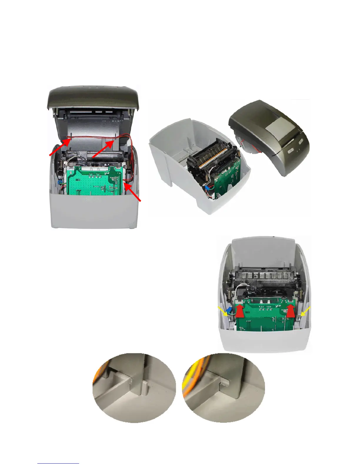
After the body case is disconnected from the base, lift the frontal part first. You will see that
the low paper sensor cable is connected to the connection board. Disconnect this cable very
carefully so it doesn't get damaged.
When reassembling the equipment, make sure that you connect the cable on the inside of the
body case as shown by the arrows (figure below, on the left); pass the cable by the right side
of the cutter mechanism, so that when the body case is remounted it doesn't squeeze the
cable, damaging it.
To remove the cutter mechanism and the
connection board, first remove the control
board cartridge then loosen the screws on the
cutter mechanism side - the ones pointed by
the yellow arrows in the picture - and push
the mechanism back alongside the connection
board, as pointed by the red arrows. The
mechanism is released and can be lifted to be
separated from the base.
The Cutter Mechanism and Connection Board
will be removed from the MP-4000 TH base.
On the back side of the mechanism, there is a
tab that keeps it attached to the base, as
shown on the pictures below.