Do you have a question about the Bender COMTRAXX COM465IP and is the answer not in the manual?
Explains manual content, intended audience, and prerequisite documents.
Details Bender's support services including first-level support and repair.
Provides contact details for technical support via phone and email for Bender products.
Outlines Bender's services for repair, calibration, and updates of their products.
Describes on-site services like commissioning, troubleshooting, and training.
Informs about available training dates and how to find them online.
Refers to Bender's general delivery and payment conditions, including software clauses.
Provides guidelines for inspecting, transporting, and storing the device safely.
Excludes warranty claims under specific conditions and emphasizes manual adherence.
Explains how to dispose of the device according to regulations (WEEE, RoHS).
Refers to a separate document for general safety instructions for Bender products.
States that only qualified personnel should work on electrical installations and warns of electric shock danger.
Details how the gateway connects devices to networks and its conversion capabilities.
Emphasizes the importance of correct address assignment and termination to prevent malfunctions.
Lists the items included in the delivery package for the gateway and manuals.
Describes the gateway's modular design, network connectivity, and support for Bender devices.
Outlines the basic functions of the device, including web interface and connectivity.
Explains features like text allocation, E-mail notifications, and documentation.
Describes support for Modbus TCP, SNMP, and control commands.
Details quick parameterization via web browser and backup file generation.
Explains fast visualization, graphical display, and system data overview.
Describes creating virtual devices with multiple channels.
Details integrating third-party devices via Modbus.
Lists various applications like system visualization, device monitoring, and remote diagnosis.
Explains integration into EDP structures and role as PROFIBUS DP slave.
Refers to the "COMTRAXX" manual for this section.
Details the device's functional description.
Explains the various interfaces (BMS, BCOM, Modbus, PROFIBUS DP) used for communication.
Describes how the gateway prepares and makes process image data available for display and transfer.
Directs users to the homepage for an updated list of compatible BMS devices.
Details communication via BMS bus and master/slave operation.
Lists key questions to address before installation, network setup, and hardware requirements.
Provides safety warnings for electrical work and general installation guidance.
Describes the types of installation supported, such as DIN rail or screw mounting.
Shows a dimensional drawing of the device.
Details the connections for power supply, BMS bus, Modbus RTU, and Ethernet.
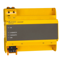
Explains the function of the LEDs on the device for status indication.
Mentions the integrated web user interface for configuration and operation.
Guides through initial power-up, web interface access, and device configuration.
Lists factory default IP addresses, netmask, gateway, and BMS/BCOM settings.
Explains how to install the GSD file required for PROFIBUS DP master configuration.
Describes the COM465DP's role as a PROFIBUS DP slave and its communication requirements.
Highlights the importance of timing control and ID number comparison for PROFIBUS communication.
Explains the COM465DP's BMS master role when BMS address is 1 for PROFIBUS communication.
Details the byte sequence formats for output (request) and input (response) data.
Outlines three methods for data access: querying measured data, registers, and writing registers.
Explains the PROFIBUS request and response structure for querying measured values.
Explains the PROFIBUS request structure for reading registers from devices.
Explains the PROFIBUS request structure for writing data to registers.
Provides examples for configuring PROFIBUS DP masters using GSD files.
Shows an example of querying a measured value from an RCMS490-D device.
Demonstrates querying a measured value during an IRDH375 alarm condition.
Illustrates querying an IRDH375 device fault, specifically an "earth connection" fault.
Explains the PROFIBUS request for querying device registers, with an example.
Details the PROFIBUS request and response for writing data to device registers.
Explains how requests are sent using Modbus TCP function code FC4 for reading input registers.
Lists Modbus exception codes and their meanings for troubleshooting requests.
Describes the structure of Modbus TCP requests, including transaction ID and function code.
Explains the structure of Modbus TCP responses, including register values.
Details the structure of Modbus exception codes for error handling.
Shows the Modbus address ranges for various BMS device parameters.
Explains the device's process image memory holding device states and values.
Details Modbus function codes FC03 and FC04 for reading data from devices and the process image.
Describes the organization of memory areas for reference values, process image, and unused space.
Explains the structure of the process image and Modbus address ranges for devices.
Details the Modbus start address calculation based on device address.
Discusses device-specific differences in channels and parameters to query.
Explains how the device type is read using a bus scan.
Details the format for date and time information received from devices.
Explains the bits indicating common alarm status and device failure.
Describes how analogue/digital channels transmit alarm, status, and measured values.
Explains the IEEE 754 representation of floating-point values for channels.
Details the coding for alarm types, test types, and status bits.
Explains the coding for units and range of validity for measured values.
Provides a table of codes for channel descriptions, alarms, and operating messages.
Describes digital information for channels 33-64, including alarm/test types and device errors.
Provides a practical example of reading a floating-point value (voltage) using Modbus TCP.
Explains the reference data records provided at virtual address 0 for configuration checks.
Shows how Modbus start addresses are assigned for reference data records.
Details the reference value stored for channel 1 (e.g., 230V undervoltage).
Details the reference value stored for channel 2 (e.g., 12.34 A overcurrent).
Explains how to interpret and swap bytes/words to correctly access floating-point values.
Provides a comprehensive table mapping values to descriptive texts for alarms and operating messages.
Explains how to send commands to BMS devices via Modbus TCP for control and status.
Shows a practical example of changing over an ATICS to a different line using Modbus control commands.
Lists common malfunctions and checks for the COM465... and COM465DP.
Provides a checklist for verifying power supply, bus connections, and configuration.
Answers common questions, like accessing the device when addresses are unknown.
States that the device contains no user-maintainable parts.
Provides instructions for cleaning the device using a soft, dry, antistatic cloth.
Presents detailed technical specifications in a tabular format.
Lists relevant standards, approvals, and certifications like ISO 9001 and UL.
Provides ordering information for different device types and function modules, including part numbers.