Installation, connection and commissioning
22
COM465IP-COM465DP_D00216_02_M_XXEN/03.2017
5. PROFIBUS DP connection (COM465DP only):
Connect the corresponding connector on the PROFIBUS cable to the 9-pin Sub-D socket (2). If
the COM465DP is at the end of the PROFIBUS DP network, you must switch the terminating
switch on the PROFIBUS connector to "ON".
6. Connect power supply:
Connect terminals A1/+ and A2/- (1) to a power supply (see nameplate and chapter "8.3 Order-
ing data").
The power supply must be protected using a 6 A fuse.
7. Position the terminal covers and click it into place.
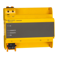
4.5 Displays and controls
4.6 COM465… web user interface
The device has a web user interface for configuring and operating the device. The many features of
the web user interface are described in the manual "COMTRAXX".
COM465DP-24V, COM465IP-24V
Pay attention to the connection polarity!
Use power supply units with safe separation only!
COM465DP-230V, COM465IP-230V Connection polarity is irrelevant.
Item Function
I
"ON" LED: Flashes during the start process.
The LED illuminates continuously as soon as the device is ready for
operation.
II
LEDs indicate activity on the various interfaces. The LED "PROFI-
BUS" exists only in the COM465DP.
ON
PROFIBUS
ETHERNET/IP
MODBUS/RTU
BMS
ON
ETHERNET/IP
MODBUS/RTU
BMS