Installation, connection and commissioning
21
COM465IP-COM465DP_D00216_02_M_XXEN/03.2017
4.4 Connecting device
For UL applications, the following must be observed:
– Maximum ambient temperature: 55 °C
– Use 60/70°C copper lines only
Make the connection as follows:
1. Remove terminal covers of the device
2. BMS bus connection:
Connect the terminals ABMS and BBMS (4) to the BMS bus (A to A, B to B). If the COM465… is at
the end of the BMS bus, you must switch the terminating switch on the device (7) to "ON".
3. Modbus RTU connection:
Connect the terminals AMB and BMB (3) to the Modbus RTU (A to A, B to B). If the COM465… is
at the end of the bus, you must switch the terminating switch on the device (6) to "ON".
4. Establish connection with PC and BCOM:
Connect Ethernet cable (RJ45) to the COM465… (5) and connect to the PC network. It is recom-
mended to use at least on Ethernet cable of category 5 (Cat. 5).
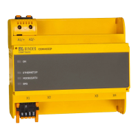
1 Power supply: see nameplate and chapter "8.3 Ordering data"
2 PROFIBUS DP connection (COM465DP only)
3 Modbus/RTU interface: Terminals AMB and BMB
Plug X1
4 BMS bus (Bender measuring device interface): Terminals ABMS and BBMS
5 Ethernet connection (RJ45) for the connection to the PC network as well as to
BCOM
Plug X2
6 Modbus RTU terminating resistor switch
7 BMU bus terminating resistor switch
8 Micro-USB interface (currently has no function) Plug X3
9 Mini-HDMI interface (currently has no function) Plug X4
COMTRAXX
A1/+
X1 X2
X3 X4
A2/-
ON
PROFIBUS
ETHERNET/IP
MODBUS/RTU
BMS
PROFIBUS DP
COM465DP
X1
AMB
BMB
ABMS
BBMS