Bennett 3000 Spec 300 Series Instruction Manual Service & Troubleshooting
59
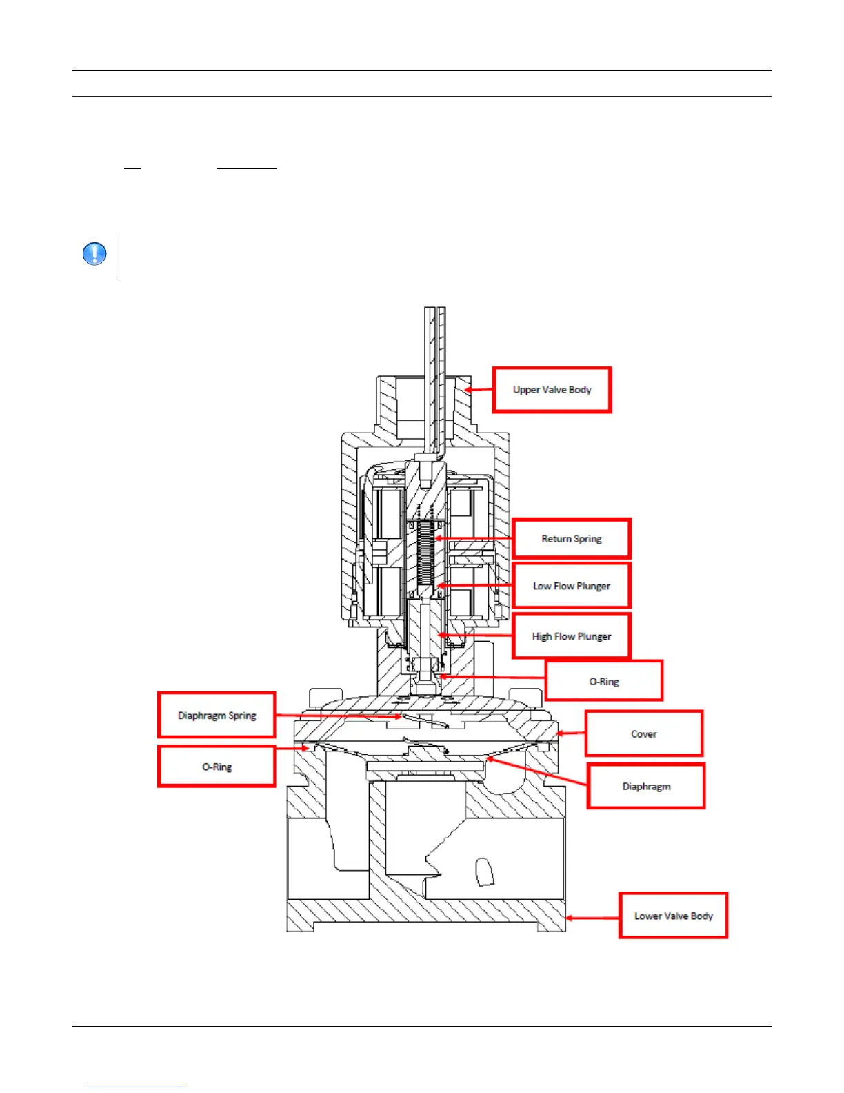
COMPONENT DESCRIPTION
A 3-wire connection connects to J10 (side 1) and/or J7 (side 2) of the 719 CPU for valve control. This valve is also the Side 1 valve for the
second product when the dispenser is configured as 2 side and 2 grades (e.g. diesel + DEF). Note: Always make sure that the correct valve
is connected to this harness. The harness connectors are clearly marked.
Pin Description
1 (black) Main Valve Output (Fast Flow Coil/Plunger)
2 (yellow) Dribble Valve Output (Slow Flow Coil Plunger)
3 (red) +24VDC Common
IMPORTANT: +24VDC is always present on the red wire (unless this is a 120 or 240-volt A.C. valve). The coils are not
energized until the system provides a “ground” for those coils. When the CPU wants to open either the
fast or slow flow it turns on a Field Effect Transistor (FET) to provide a ground for that coil.