Bennett 3000 Spec 300 Series Instruction Manual Service & Troubleshooting
61
HOW TO TEST THE VOLTAGE
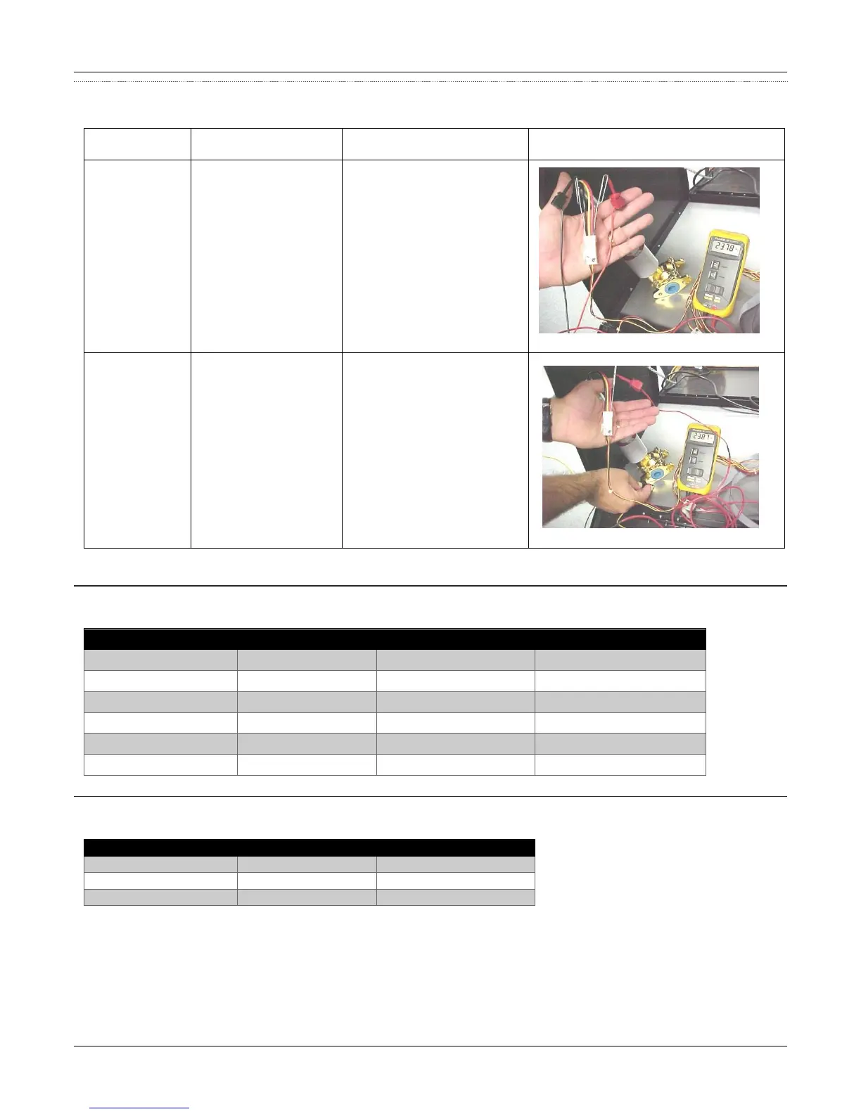
The valves can be tested for proper voltage readings via Wire to Wire or Wire to Chassis. Refer to the table below for a brief instruction.
On the top of the valve
where the valve harness
connects to each valve.
1. Use a digital voltmeter set
the scale for dc voltage.
Highest expected voltage is
+24VDC.
2. Push the multi-meter
probes into the harness
connector for that valve or
you can use paper clips.
Use the wire harness wire
to the chassis of the
equipment.
1. Measure the colored wire
by either pushing your
probe into the connector or
by using a paper clip
2. Ground the black lead to
the chassis of the
equipment.
2-STAGE VALVE VOLTAGE READINGS
Refer to the chart below for normal voltage readings. The following chart reflects a +24VDC valve. If you are testing a +120VAC valve, you
can substitute 120 volts where you see 24 volts in the chart.
PROPORTIONAL VALVE VOLTAGE READINGS
Refer to the chart below for normal voltage readings. The following chart reflects a +24VDC valve. If you are testing a +120VAC valve, you
can substitute 120 volts where you see 24 volts in the chart.
Yellow to Red Wire = 0 VDC
Black to Red Wire = 0 VDC
Yellow to Chassis = 0 VDC
Black to Chassis = 24 VDC
Yellow to Chassis = 0 VDC