TEBEVERT III INVERTER SYSTEM (120 VDC)
07.11.2011 18 028-0009-006
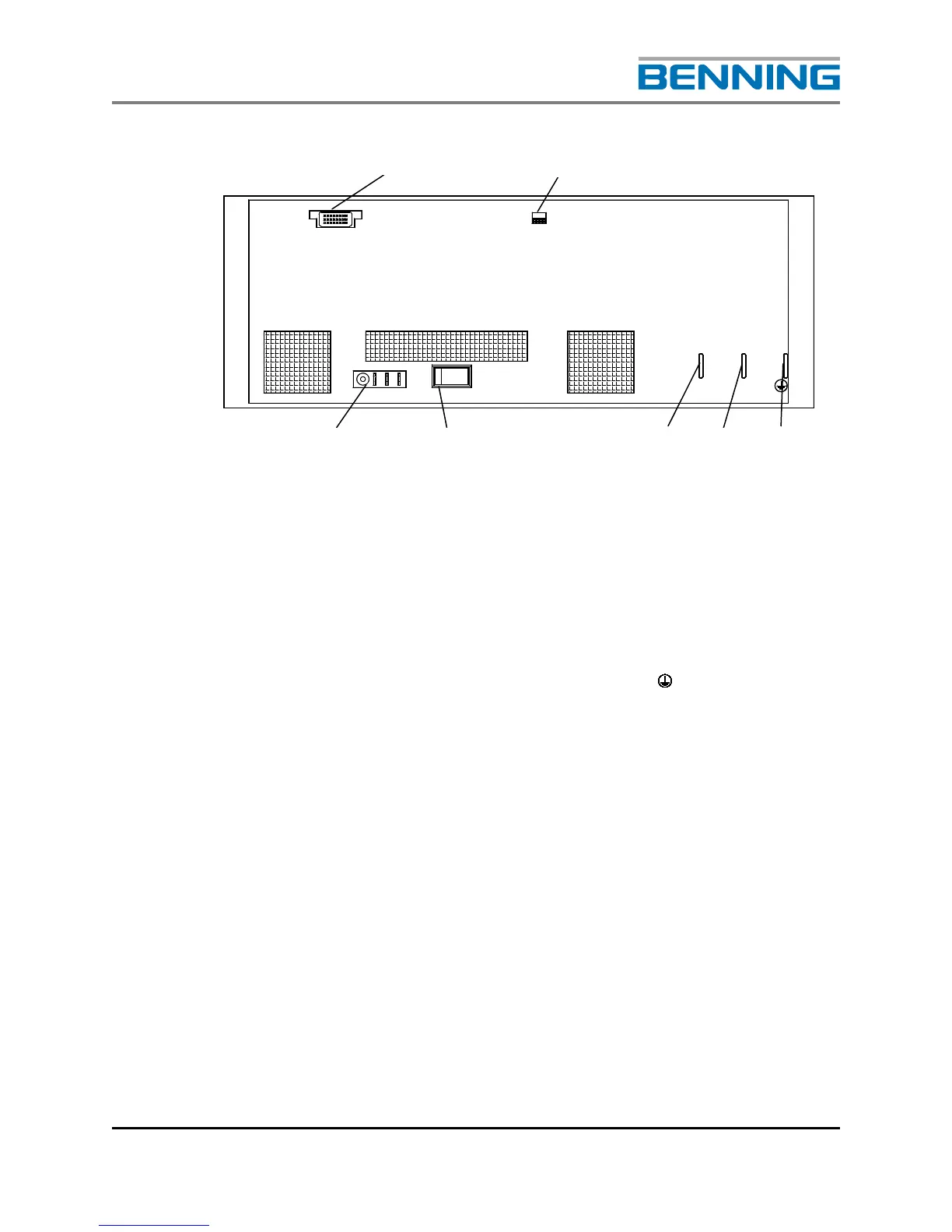
Fig. 8: Rear view of the modular inverter unit
1 Data connector (X3)
2 DIP switch to set the frequency (S2) (Refer to Section 4.1
for details)
3 Contact blade for the protective earth (X1: )
4 Contact blade for the DC input (X1: -)
5 Contact blade for the DC input (X1: +)
6 Inverter Output circuit breaker (F1)
(Placed above of X2 for the 5.0kVA inverter)
7 Output connector (X2) 3 poles (5 poles for 5KVA/120VAC
inverter)
X 3
X 2
0
F1
X 1