TEBEVERT III INVERTER SYSTEM (120 VDC)
07.11.2011 23 028-0009-006
3.6.2 TERMINALS AND OPERATING ELEMENTS
All terminals and operating elements are on the front panel or rear of the
SBS unit.
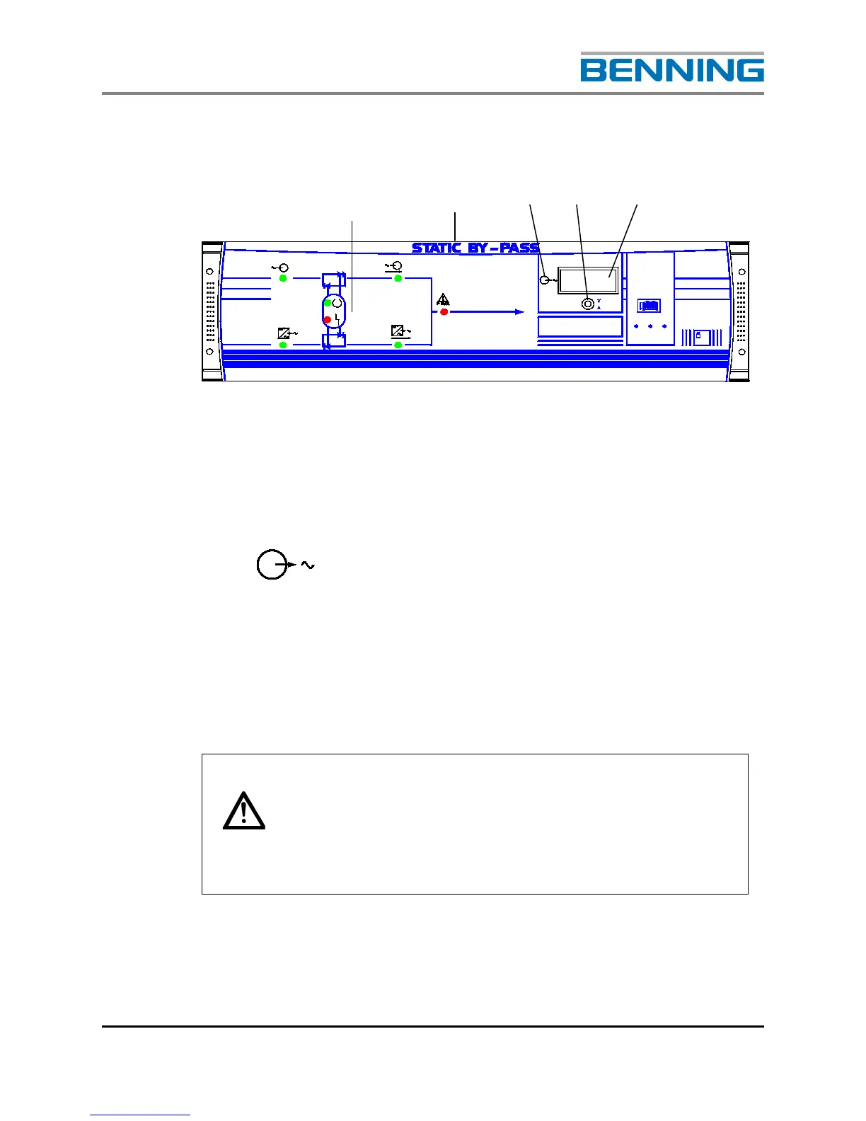
Fig. 11: Front view of the Static By-Pass Switch (SBS)
1 Display and signalling panel
2 Model designation
3
Indicates the system output
4 Selector switch to display either the inverter output voltage or
inverter output current. According to the position of switch, the
output voltage (V) or the output current (A) is displayed
5 Digital volt/ammeter (displays output voltage or the output current)
The 120/240VAC configuration utilizes input/output
transformers to convert the input and output voltages from
the nominal 120VAC. Therefore the voltage and current
displayed on the Digital Voltmeter shall display the 120VAC
component only.
1