TEBEVERT III INVERTER SYSTEM (120 VDC)
07.11.2011 40 028-0009-006
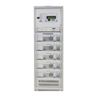
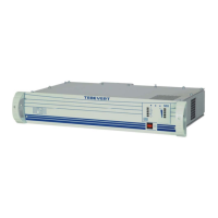
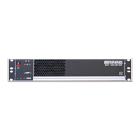
4.4.2 INSTALLATION OF THE INVERTERS
The weight of each inverter is approx. 35kg (77lbs). The
unit may only be lifted and transported using the carrying
handles built into each side of the unit. DO NOT carry or
lift the unit using the handles on the front panel!
Before the inverter unit is installed, any materials used to protect the unit
during transportation must be removed. The guiding rails on the base of
the inverter shelf and under the inverters ensure the exact positioning of
the modular inverter unit. The unit is slowly pushed in past a slight
resistance until the front panel is flush with the frame of the cabinet. All
electrical contacts have then been made. The inverter is then fixed into
the cabinet with four screws (supplied).
Any free slots reserved for future inverter upgrades must be covered with
dummy plates. These plates must be secured with four screws (supplied).
4.5 SWITCHING ON THE INVERTER SYSTEM
Before the AC by-pass is connected and the inverters are switched on, it
must be verified that the manual maintenance by-pass switch is in position
“0” (UPS operation). In this position the Static By-Pass Switch (SBS) is
mechanically locked and cannot be pulled out of the cabinet.
The load circuits should not yet be connected and all the inverters should
be switched off. Normally, the Static By-Pass Switch (SBS) should be set
to the operation mode "inverter priority" (See Section 4.2).
Step one, the DC supply should be switched on, all the LEDs on the SBS
light up for a short time. (Reset of the internal processor!) Afterwards,
only the LED "FAULT" is lit and the DVA indicates the voltage or current to
be "0".
Second, the AC by-pass should be switched on. The LEDs "MAINS
VOLTAGE PRESENT" and "MAINS OPERATION" are lit as well as the LED
"FAULT".