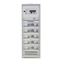
TEBEVERT III INVERTER SYSTEM (120 VDC)
07.11.2011 46 028-0009-006
5.4.1 SBS TEST ACTIVITIES
Action Result
Switch off the mains from the by-pass. The green LED “MAIN VOLTAGE
AVAILABLE” and “READY FOR
OPERATION” go out and the red LED
“FAULT” lights up. Also an outgoing
alarm shall be given after approximately
10 seconds.
Connect a voltmeter to the output of
the inverter system.
The reading of the voltmeter and of the
display shall read 120VAC ± 5%. (See
Important Note below)
Switch on the mains for the
by-pass
AVAILABLE”, “INVERTER
OPERATION” light up and the
red LED “FAULT” goes out.
The reading of the by-pass
volt/ammeter shall be 120 or
120/240VAC
10%. The
alarm ceases.
Switch off all inverter modules. The green LEDs “INVERTER VOLTAGE
AVAILABLE” and “INVERTER OPERATION
go out, the green LED “MAINS
OPERATION” lights up and the red LED
“FAULT” lights up. Also and outgoing
alarm will be given.
Connect a voltmeter to the output of
the inverter system.
The reading of the voltmeter shall be
120 or 120/240VAC ± 5%.
Switch on all inverter modules. The green LEDs “INVERTER VOLTAGE
AVAILABLE”, “INVERTER OPERATION”
and “READY FOR OPERATION light up,
and the green LED “MAINS OPERATION”
and the red LED “FAULT” go out. The
alarm ceases.
The 120/240VAC configuration utilizes input/output
transformers to convert the input and output voltages from
the nominal 120VAC. Therefore the voltage displayed on
Digital Voltmeter shall display the 120VAC component only.