TEBEVERT III INVERTER SYSTEM (120 VDC)
07.11.2011 39 028-0009-006
4.4.1 INSTALLATION OF THE STATIC BY-PASS SWITCH
(SBS)
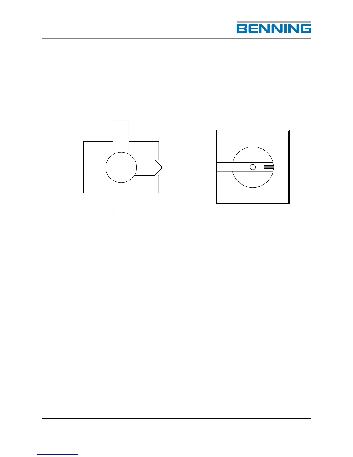
At the time the Static By-Pass Switch (SBS) is installed, the operating
handle of the manual maintenance by-pass switch is attached. The handle
is installed on top of the SBS unit using supplied four (4) M4 x 8mm
screws. Position the switch mechanism and the operating element in the
following position.
Fig. 14: Installation positions of the locking mechanism and the operating element
Using the guiding rails located on the base of the mounting shelf, slowly
push the SBS unit into the shelf until the front panel is flush with the
frame of the cabinet. This should require minimal effort. All electrical
contacts have been made and the operating element of the manual by-
pass switch is connected to its rotation axle. The SBS is fixed into the
cabinet with four screws (supplied).