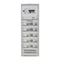
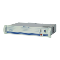
TEBEVERT III INVERTER SYSTEM (120 VDC)
07.11.2011 55 028-0009-006
7.2.5 SHORT-CIRCUIT BEHAVIOR
The inverter is permanently short-circuit proof. Short-circuits are a special
type of overload. At the time of the short-circuit, the current is limited for
5 seconds to 2.8 times the nominal effective current. During this period,
the short-circuit current can trigger the AC load protection circuits in the
customer provided AC distribution.. After approx. 5 seconds have elapsed,
the power unit of the inverter switches off. A restart of the inverter is only
possible when the inverter has been switched off with the main On/Off
switch, all LED´s on the front panel are extinguished, and the inverter has
then been switched On again.
If the short-circuit persists, this procedure is repeated.
When the inverter is operated with an Static By-Pass Switch (SBS), the
connected AC bypass supplies the short-circuit current.
7.3 ELECTRONIC SWITCHING/SBS UNIT
The electronic switching unit accurately monitors all the relevant data of
the inverter system. This includes:
Inverter operational states
AC by-pass voltage
Inverter voltage
AC by-pass frequency
phase position between the inverter output and the mains
level of the load
This information is fed to an internal controller, which controls the Static
By-Pass Switch (SBS) via a logical trigger switching the AC by-pass or the
inverter output voltage through to the load equipment. If the system is
functioning correctly, the voltage, which has been pre-selected by the
setting of the operation mode, is switched through the Static By-Pass
Switch (SBS), i.e. "mains priority" or "inverter priority".
In addition to the visual indicators (LEDs), the SBS also controls dry
contact alarm relay A setting option is used to select whether this
messaging is a collective fault message from the SBS and the inverter, or
a single fault message of the SBS. This message follows the visual
indication with a delay of approximately 10seconds.
The cause of these faults may be: