TEBEVERT III INVERTER SYSTEM (120 VDC)
07.11.2011 12 028-0009-006
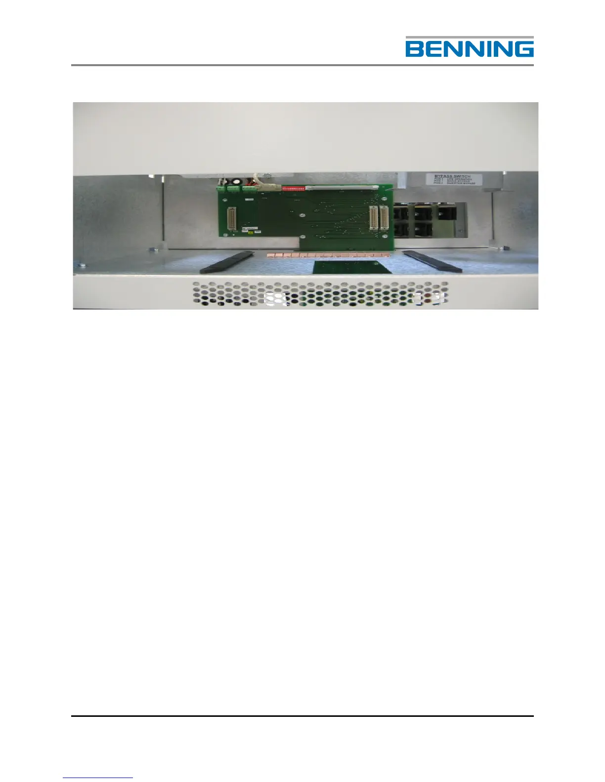
3.3 SBS MODULE SHELF
• Terminal block for the connection of the auxiliary DC supply to the SBS (X26)
• Terminal block for the voltage-free collective fault messaging system of the
inverter system (X25)
• Terminal block for the connection of the auxiliary contact signifying the by-
pass switch is in the “manual by-pass inverter” position (X27)
• Terminal block for the connection of the auxiliary contact signifying the by-
pass switch is in the "manual by-pass mains" position (X28)
• D-SUB connector for the optional connection of the inverter system to the
MCU remote monitoring system (X23)
• DIP switches, without function (S1)
• Data line to the inverter slot (X10) (This is used if there are inverters
arranged above the SBS. Not standard!)
• Manual by-pass switch with locking mechanism for the SBS (Q10)
• Female connector for the neutral contact mains input (N)
• Female connector for the neutral contact mains input (N)