TEBEVERT III INVERTER SYSTEM (120 VDC)
07.11.2011 32 028-0009-006
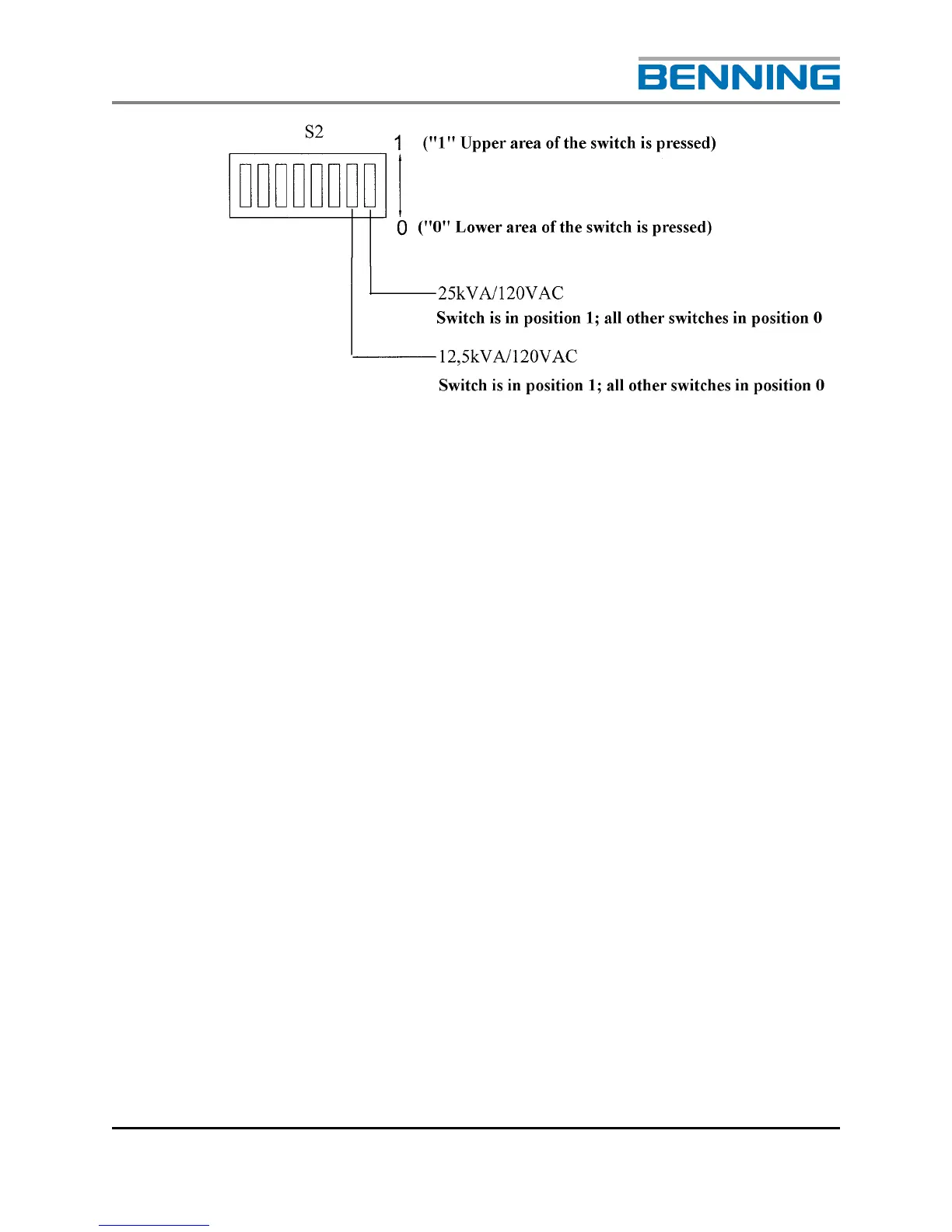
4.3 PANEL WRITING
The cable is fed into the inverter system from above or below, according
to the model. The size and location of the terminal blocks and distribution
assemblies are configuration dependant, refer to Elevation drawing for
exact requirements. For the cross-sections and the recommended over-
current protection the following values must be observed. The
recommended cable sizes shown below meet National Electrical Code
(NEC) Table 310-16 requirements, however please remember that larger
size cables may be required in order to meet site voltage drop
requirements. It is recommended that if a system can be expanded with
additional inverters in the future, the initial AC wiring be sized for the
maximum number of inverters.
Larger cross-sections should be used to reduce the effects of voltage-drop
depending on the conditions at the installation site than would normally be
necessary due to the current
.
There are three options for the DC input section of the Inverter system.
• Bulk input accepting up to 750MCM two-hole lugs, two per pole in a back-to-back
configuration. The hole pattern is designed for 3/8” holes at 1” cc. EC-701 must
be ordered for this.
• Individual DC input per inverter module using screw compression type terminal
blocks. These terminal blocks accept up to one 4/0 stranded cable.
• Individual DC input per inverter module accepting two-hole lugs with 3/8-16
studs on 1”cc. These terminal blocks accept up to one 4/0 stranded cable per
pole.