TEBEVERT III INVERTER SYSTEM (120 VDC)
07.11.2011 19 028-0009-006
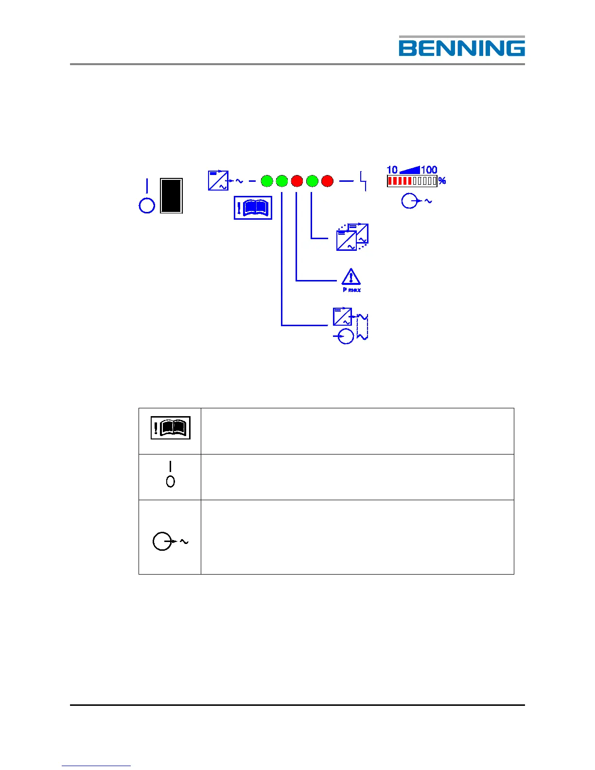
3.5.3 SIGNALLING
On the front panel of the inverter there is a bar graph indicator and LED´s
that are used to indicate the operating state of the inverter.
Fig. 9: Operating and signalling panel
This symbol indicates that all the points in this operating
manual must be observed at all times.
Indicates the position of the inverter's power switch, ON / I
or OFF / O
Indicates the inverter output voltage is present. The bar
graph indicator shows the output current of the inverter in
steps of 10% relative to the maximum output current of
the inverter.