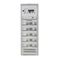
TEBEVERT III INVERTER SYSTEM (120 VDC)
07.11.2011 56 028-0009-006
disturbances in the AC by-pass supply
disturbances in the inverter / inverter system
disturbances in the SBS
The reset of the dry contact alarm relay occurs without a delay. To permit
operation of the SBS via the remote monitoring system MCU, an additional
unit (satellite card) must be installed. Through this optional unit,
operational states and measurement values of the SBS and the associated
inverter system are transmitted to the remote monitoring system via a
serial interface to RS485 standard.
In the standard design, 6 different types of status information are
transmitted, resulting from the linkage of the various status data.
The transmitted status information comprises:
• Inverter operation
• SBS warning
• SBS fault
• Overload
• Faulty output voltage
• SBS blocked
In addition, 15 detected or calculated measuring values are transmitted.
• Heat sink temperature SBS
• Inverter voltage
• AC by-pass voltage
• Output voltage SBS
• Output current SBS
• Output current inverter 1 – inverter 5
• Active power
• Apparent power
• Reactive power (calculated)
• Crest factor
• Output frequency
All indicated states and measuring values of the inverter system can be
further processed and evaluated using the service software of the remote
monitoring system.
Redundancy function for the SBS Satellite function (5 kVA and 2.5 kVA inverters)