TEBEVERT III INVERTER SYSTEM (120 VDC)
07.11.2011 24 028-0009-006
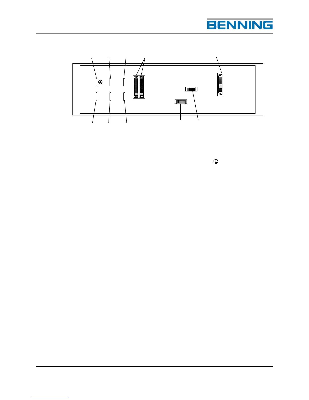
Fig. 12: Rear view of the Static By-Pass Switch (SBS)
1 Contact blade for the protective earth (X1: )
2 Contact blade for the SBS output (X1: N)
3 Contact blade for the inverter input (X1: 1L)
4 Female connector for the data bus (X3; X4)
5 Female connector for the auxiliary DC supply and voltage-free
fault messaging system
(X5)
6 DIP switches for system settings (S1) (Refer to Section 4.2 for
details)
7 DIP switches for system settings (S2) (Refer to Section 4.2 for
details)
8 Contact blade SBS output (X1: L)
9 Contact blade mains input (X1: L1)
10 Contact blade neutral contact, mains input (X1: N) (not included
on 25.0kVA unit, part no. 120418)
L1
N
1L
X 3
X 4
S 2
1 2 3 4 5
10 9 8