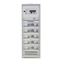
TEBEVERT III INVERTER SYSTEM (120 VDC)
07.11.2011 44 028-0009-006
The internal temperature will rise and
the inverter module will automatically
switch off.
Disconnect the load bank and re-start
the inverter by means of the On/Off
Switch.
The green LEDs “OUTPUT VOLTAGE
AVAILABLE” and PARALLEL OPERATION”
will light up.
1. Switch off the inverter.
2. Short circuit the output of the
inverter system by connecting a cable
across the output terminals.
(WARNING! Verify the
commercial AC input to the AC by-
pass is turned-off.) The cable shall
be the same gauge as the normal load
cables.
3. Switch on the inverter.
The inverter system shall pass into
current limit and shall automatically
switch off after approximately 40 to 50
seconds.
Remove the short circuit and restart
the inverter module by means of the
On/Off switch.
The inverter restarts
Switch off the inverter module The inverter shuts off.
The 120/240VAC configuration utilizes input/output
transformers to convert the input and output voltages from
the nominal 120VAC. Therefore the voltage displayed on
Digital Voltmeter shall display the 120VAC component only.
Repeat test 5.3.1 for each inverter module installed.