TEBEVERT III INVERTER SYSTEM (120 VDC)
07.11.2011 53 028-0009-006
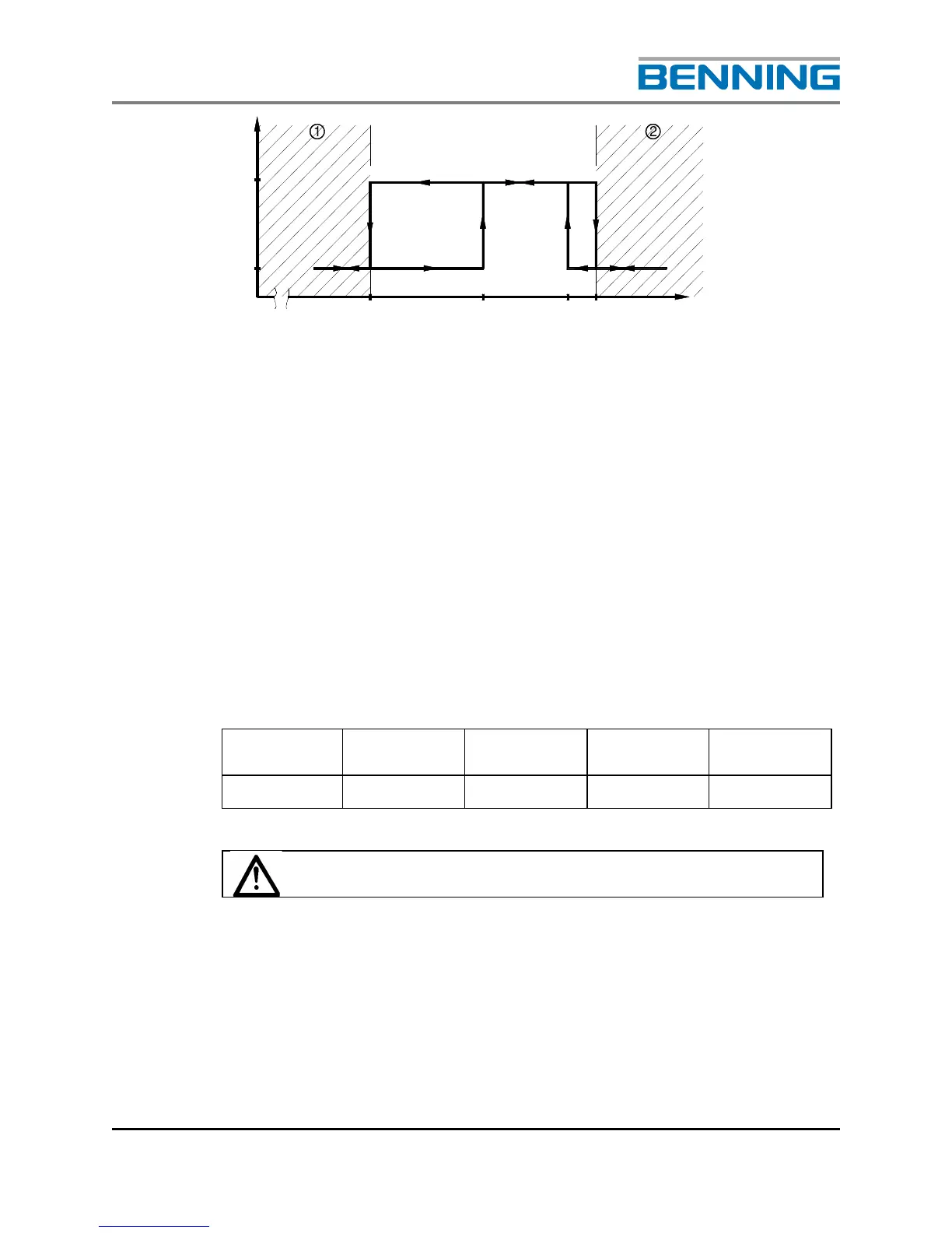
1 Under voltage range 2 Over voltage range
Fig. 17: Switching thresholds for over voltage and under voltage monitoring system
Figure 17 shows the main principles of the system. If over voltage is
applied, the inverter switches off at U2. Once the voltage has dropped to
below U3, the inverter switches on again automatically.
After switching off as a result of under voltage (U1), the inverter switches
on again only after the input voltage U0 is reached. This value, U0, must
also be available when the inverter is switched on at the main switch. This
ensures that the unit does not start up briefly when the battery is not
charged.
Because of component variances and setting tolerances, the following
voltage ranges apply for the switching thresholds.
Nominal
input voltage
U1 U0 U3 U2
U
N
= 120V
100.8V-103.3V 121.3V-123.8V 142.5V-145.5V 148.5V-151.5V
The unit cannot be switched on when input voltages are
below U0!
EIN/
ON
U0
U2
U3
1 Under voltage 2 Over Voltage