Instruction Manual
2929
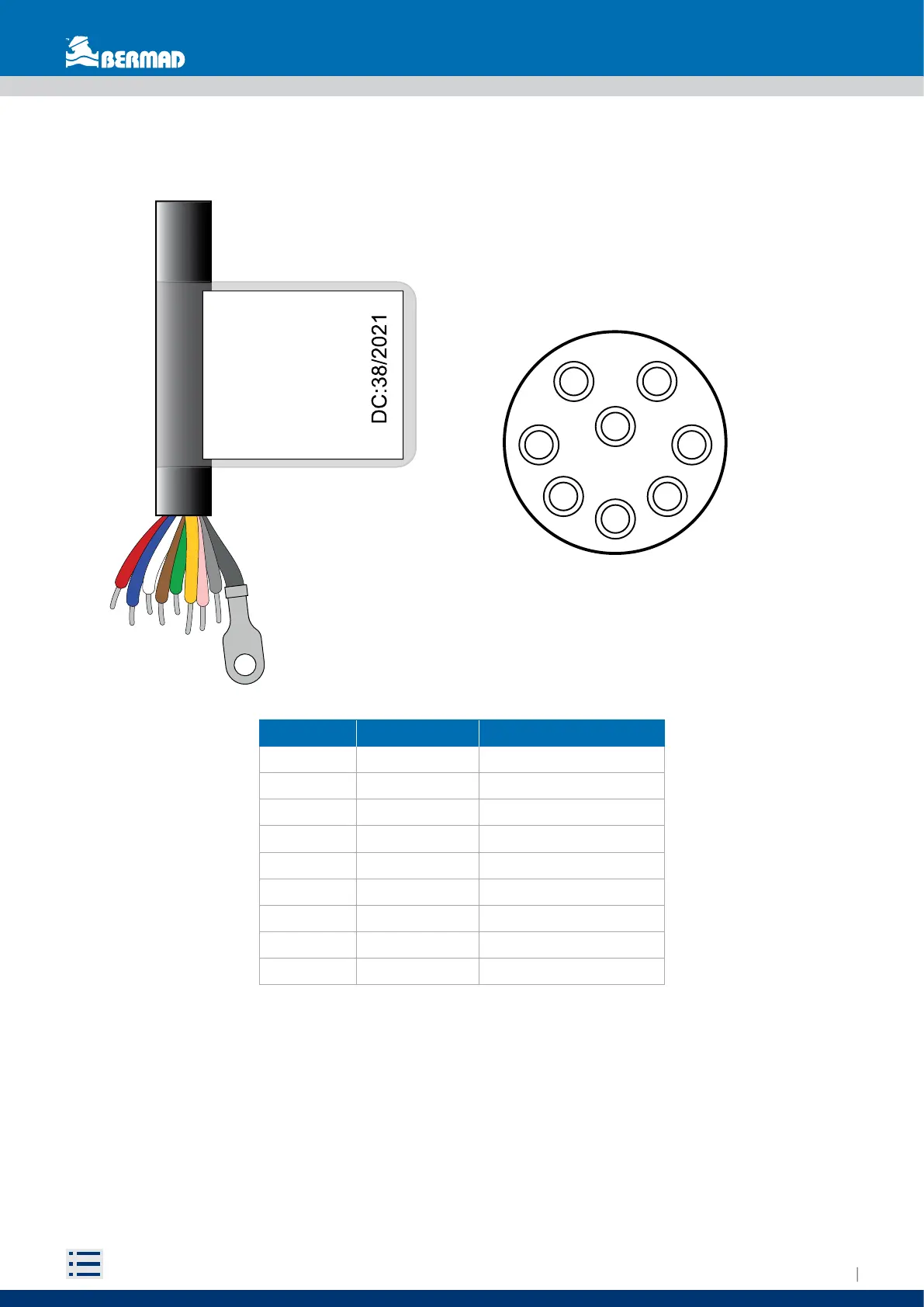
The manufacturer has identified all the power cables and signal cables that have to be connected by
marking them with a colour in order to ease the identification of the correct connection terminals (Fig. 38).
Table 1 Cables and Connection Terminals Identification
Note: The cables supplied by BERMAD are not suitable for being run directly underground and/or underwater,
and must not be exposed to direct sunlight. The technician in charge must therefore provide suitable
protections such as: corrugated pipes, raceways, or shielded cables.
Wire Color Connector Pin Function
Red A Supply voltage + 12Vdc
Blue H Supply voltage -
White C Pulse output 1
Brown B Pulse output 1
Green G Pulse output 2
Yellow F Pulse output 2
Pink D RS485 wire B
Grey E RS485 wire A
Sheild - Sheilding
M10
Red................12Vdc+
Blue................12Vdc-
White.....Pulses P1S1
Brown....Pulses P1S1
Green....Pulses P2S2
Yellow....Pulses P2S2
Pink..............RS485 B
Grey.............RS485 A
Shield.................GND
AG
BF
E C
H
D
Fig. 39 Cable label Fig. 40 Connector Pin-Out