M10
Instruction Manual
18
4.3 INSTALLATION CONDITIONS
4.3.1 Positioning in relation to the plant
To ensure optimal working conditions, the flowmeter must be installed correctly inside the system.
Correct and incorrect installation positions are described and illustrated below.
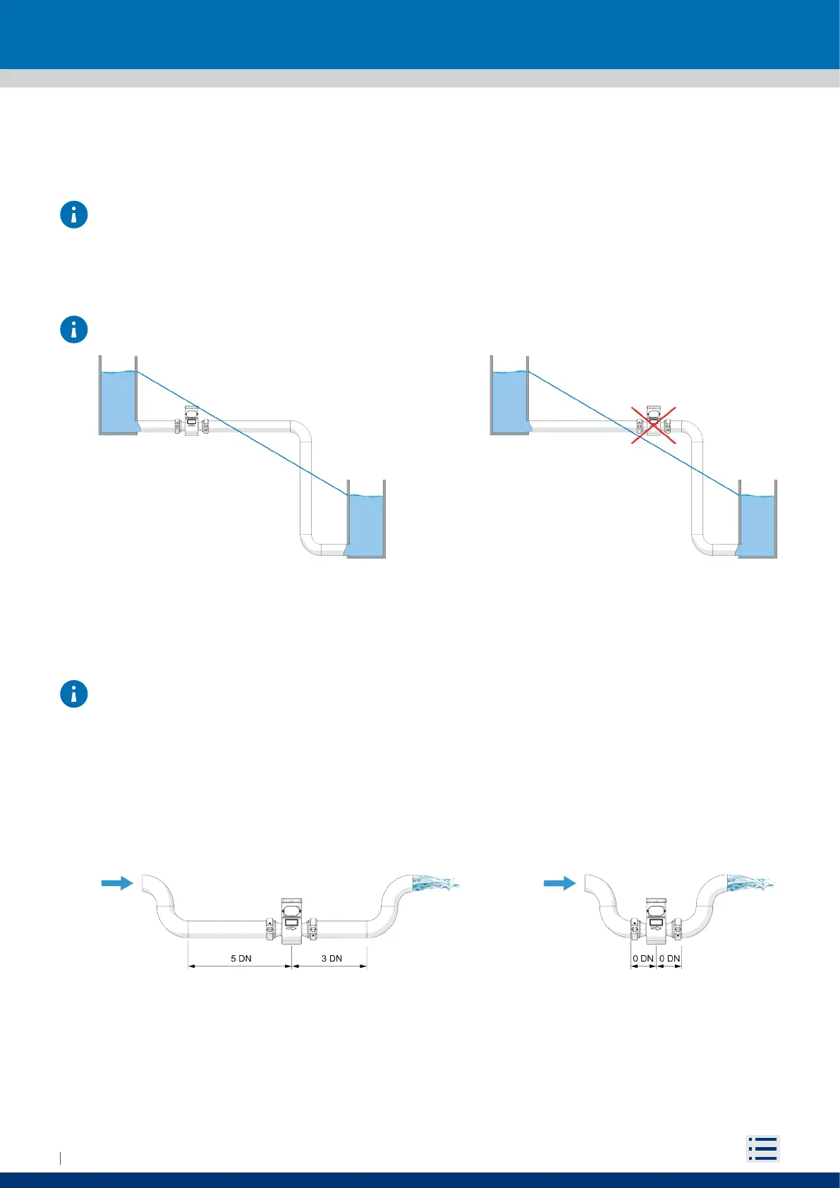
The flowmeter must remain below the hypothetical blue line (level line), which connects the two levels of
fluid to be measured (Fig. 9).
NOTE: Avoid placing the flowmeter above the piezometric level line (Fig. 10).
4.3.2 Important guidelines for correct installation
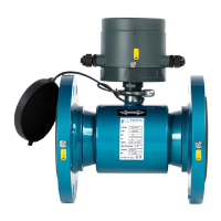
The M10 meter is designed to have the IP68 protection degree only when properly closed and tightened.
The manufacturer does not assume any responsibility for an improper closing by third parties.
For correct working conditions, please follow the important guidelines shown in the following figures.
Improper installation may result in an inaccurate measurement.
For partially filled pipes or with downward flow and free exit, the flowmeter should be placed in a
U-shaped tube (Fig. 11).
Fig. 9 Correct position Fig. 10 Incorrect position
Ideal installation
Fig. 11 Installation on U-shaped tube
Installation in limited spaces