M10
Instruction Manual
28
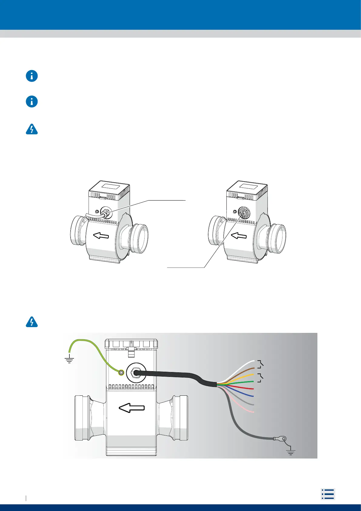
4.6 ELECTRICAL CONNECTION
In order to properly connect electrical elements of the M10 meter to the power supply and I/O connections
please refer to the wiring diagram shown in paragraph 4.6.1 (Fig. 38).
The use of cables not supplied or certified by BERMAD may jeopardize the correct functioning of the system,
and it will void the warranty.
All interventions on electrical connections must be performed only when the device is disconnected from
the mains and/or battery.
M10 meter is available with 2 dierent connection option:
2m preinstalled shielded cable
8 pin connector (optional cable is available as accessory)
Fig. 37 Connection option
4.6.1 Wiring diagram
All interventions carried out on the electrical junction box or electrical components must be performed by
properly trained specialized personnel.
Fig. 38 Electrical Wiring
PreConnected
8 wires shielded
cable
CABLE
VERSION
CONNECTOR
VERSION
8 poles bayonet
connector
A
B
Rs485
+
-
PULSES
neg pos
CABLE
Shield
PreConnected
8 wires shielded
cable
CABLE
VERSION
CONNECTOR
VERSION
8 poles bayonet
connector
A
B
Rs485
+
-
PULSES
neg pos
CABLE
Shield