M10
Instruction Manual
36
5 METER PROGRAMMING
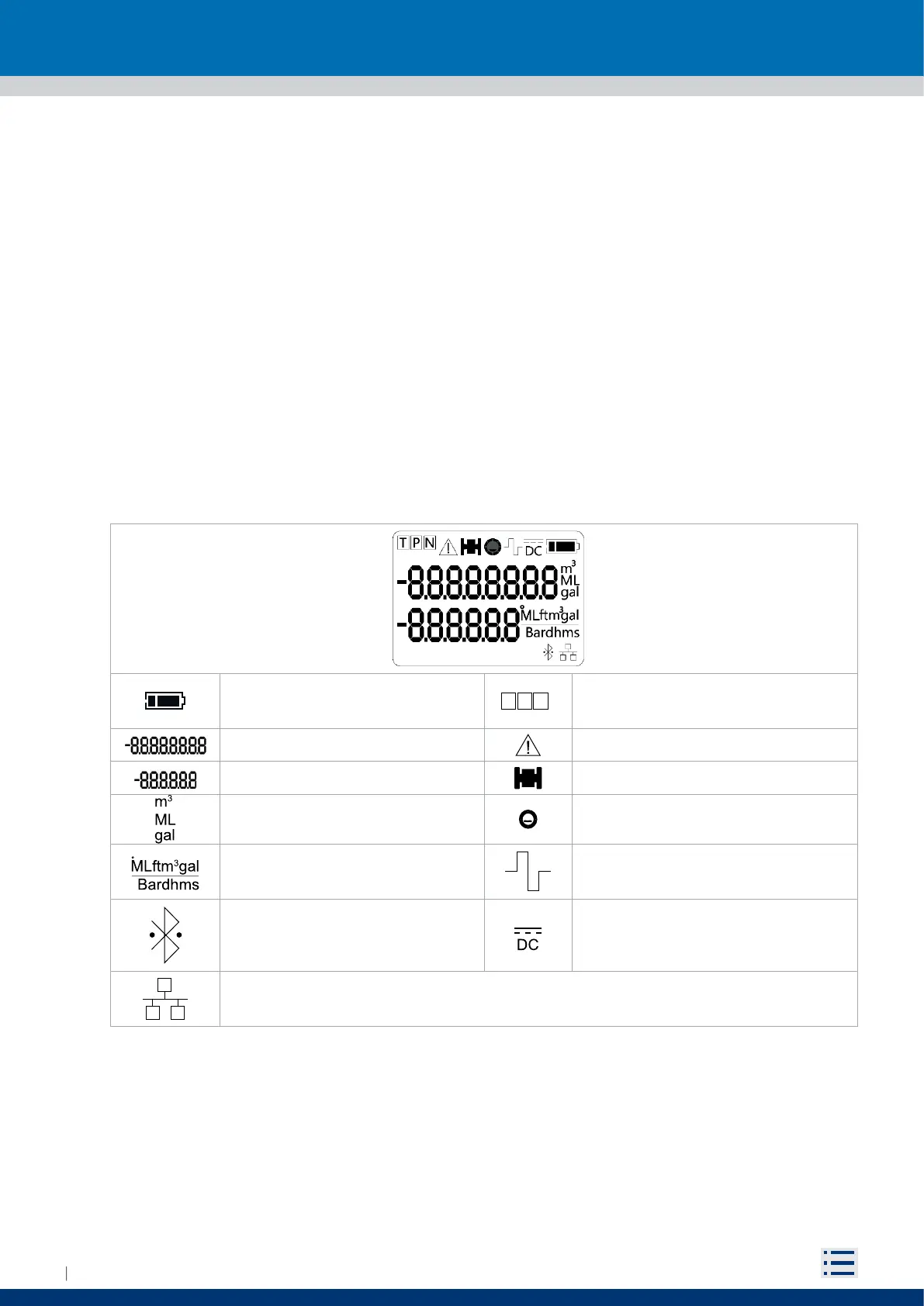
5.1 DISPLAY
M10 is equipped with a two rows segment display and a magnetic switch (reed) on the right side of the display.
The LCD can visualize an 8 and a 6 digits numbers plus several information icons, allowing the user to
display several information and set many parameters. On details, it is possible to show:
Instantaneous flowrate
Positive totalizer (T+)
Negative totalizer (T-)
Partial positive totalizer (P+)
Partial negative totalizer (P-)
Net totalizer (N)
Time & date
Parameters corresponding code and value
By swiping the magnet, it is possible to switch display views and execute some basic operations. Four
views are available:
Measurement views (“5.3 USER INTERFACE”)
Converter’s settings (“5.5 FUNCTIONS”)
Firmware’s updating view (“5.9 FIRMWARE UPDATE”)
Meter reset (“5.10.1 Reboot”)
Battery charge icon: See page 45
T P N
T: Totalizer
P : Partial totalizers
N : Net totalizer
8 digits number Generic error icon
6 digits number Sensor failure icon
Volume technical unit Empty pipe icon
Flow rate technical unit
Sleep/awake icon:
On→ awake
O→ sleep mode
Bluetooth icon:
1s flashing→ Initializing
Fixed → Ready configured
2s flashing → Connected
DC mains icon:
On→ meter powered by DC mains
RS485 icon:
Flashing→ Communicating
Fixed→Waiting for communication